
Radiation image storage panel having a particular layer arrangement

a technology of radiation image and storage panel, which is applied in the field of radiation image storage panel, can solve the problems of increased unsharpness of emitted light, inability to adjust the screen, etc., and achieve the effect of excellent sharpness and no disadvantages

Inactive Publication Date: 2005-08-09
T2PHARMA GMBH
View PDF8 Cites 12 Cited by
  • Summary
  • Abstract
  • Description
  • Claims
  • Application Information

AI Technical Summary

Benefits of technology

"The present invention provides a radiation image storage panel that has excellent sharpness and can be used repeatedly for a long time, even in severe manutention circumstances. The panel includes a layer of storage phosphor particles dispersed in a binding medium, and adjacent to a support having reflective properties. The panel also includes an antihalation undercoat layer and an adhesion improving layer between the layer of storage phosphor particles and the support. The adhesion improving layer is hardened to a lesser extent than the antihalation undercoat layer. These features make the panel more robust and reliable for use in various medical applications."

Problems solved by technology

Especially the phosphor layer thickness can give rise to increased unsharpness of the emitted light, this being the more unfavorable if the weight ratio between the amount of phosphor particles and the amount of binder decreases for the same coating amount of said phosphor particles.
Measures in order to provide sharper images by enhancing the weight ratio amount of phosphor to binder, e.g. by decreasing the amount of binder, however lead to unacceptable manipulation characteristics of the screen, due to insufficient elasticity and brittleness of the coated phosphor layer in the screen.
A disadvantage however resulting from the (mostly obligate) use of differing binder material in both of said storage phosphor and AHU layers is its lack for a perfect adhesion of both layers, more especially in view of manipulation and repeated use (re-use) of storage phosphor panels.

Method used


Image

  • Radiation image storage panel having a particular layer arrangement

Examples


examples

[0093]While the present invention will hereinafter be described in connection with preferred embodiments thereof, it will be understood that it is not intended to limit the invention to those embodiments.

[0094]Composition of the antihalation layer (AHU):

[0095]

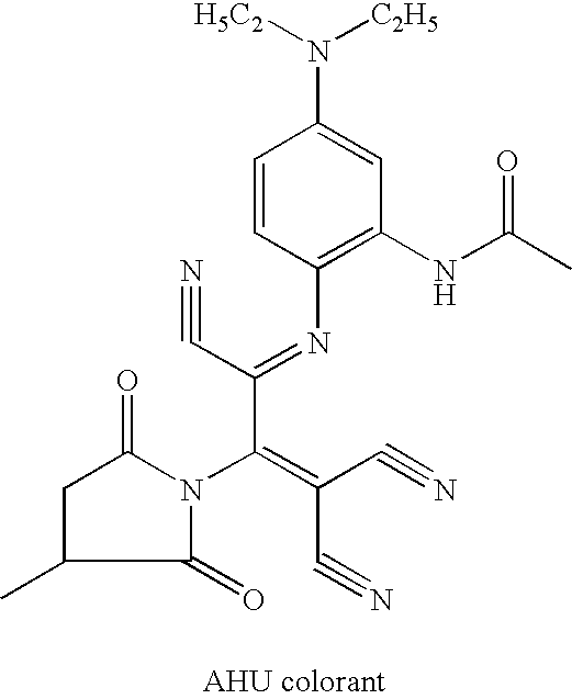
ingredientcomparativeinventive(manufactured by)AHU (wt %)AHU (wt %)Mowilith CT5 (Hoechst)8.45.6Cymel 300 (Cyanamid)2.85.6p-toluenesulfonic acid0.30.4(Riedel-de-Haen)AHU colorant (AGFA-GEVAERT)150 ppm150 ppmethanol (Silbermann)75.270.8methylethylketone (Staub)13.315.9methoxypropanol (Silbermann)01.7Mowilith CT5 is a vinylacetate-crotonic acid-copolymer; Cymel 300 is a modified melamine-formaldehyde resin (hexamethoxymethyl melamine)

[0096]Thermal curing was carried out at a temperature of at least 30 min at 90° C.

[0097]The formula of the AHU colorant has been given hereinafter.

[0098]Influence of thermal curing temperature on the non-migration percentage of the antihalation dye of the comparative antihalation layer (curing for 3...


PUM


Abstract

A radiation image storage panel. The panel has a supported layer of storage phosphor particles dispersed in a binding medium, and adjacent thereto, between the layer and a support having reflective properties, a layer arrangement of intermediate layers inbetween the layer and the support. The layer arrangement consists of an antihalation undercoat layer containing one or more dye(s), the layer being situated more close to the support, and an adhesion improving layer situated more close to the layer of storage phosphor particles, and wherein the adhesion improving layer is hardened to a lesser extent than the antihalation undercoat layer.

Description

[0001]The application claims the benefit of U.S. provisional application No. 60 / 362,264 filed Mar. 06, 2002FIELD OF THE INVENTION[0002]The present invention relates to a radiation image storage panel having, besides a fluorescent layer comprising a binder and a stimulable phosphor dispersed therein, a particular intermediate layer arrangement.BACKGROUND OF THE INVENTION[0003]In radiography the interior of objects is reproduced by means of penetrating radiation which is high energy radiation belonging to the class of X-rays, γ-rays and high energy elementary particle radiation, e.g. β-rays, electron beam or neutron radiation. For the conversion of penetrating radiation into visible light and / or ultraviolet radiation luminescent substances are used called phosphors.[0004]In a conventional radiographic system an X-ray radiograph is obtained by X-rays transmitted imagewise through an object and converted into light of corresponding intensity in a so-called intensifying screen (X-ray con...

Claims


Application Information

Patent Timeline
Patent Type & Authority Patents(United States)
IPC IPC(8): G21K4/00
CPCG21K4/00G21K2004/04G21K2004/12
Inventor VAN DEN BERGH, RUDICABES, THOMAS
Owner T2PHARMA GMBH
Learn More