Variable stage charge pump

a charge pump and variable stage technology, applied in the direction of electric variable regulation, ac-dc conversion, electric vehicles, etc., can solve the problems of wasting valuable integrated circuit area (for unnecessary extra capacitors), and power supply voltage not high enough to ensure the correct operation of the circuit. , to achieve the effect of maximizing the output curren

Inactive Publication Date: 2005-08-09
STMICROELECTRONICS SRL
View PDF12 Cites 119 Cited by
  • Summary
  • Abstract
  • Description
  • Claims
  • Application Information

AI Technical Summary

Benefits of technology

[0020]Embodiments of the invention are directed to a charge pump that has a variable number of stages. This allows the output current to be maximized for a given integration area by selecting the...

Problems solved by technology

In some electronic devices, the power supply voltage is not high enough to guarantee the correct operation of the circuit.
Both of these unknown values makes it difficult to accurately design a suitably sized charge pump.
I...

Method used


Image

  • Variable stage charge pump
  • Variable stage charge pump
  • Variable stage charge pump

Examples


Embodiment Construction

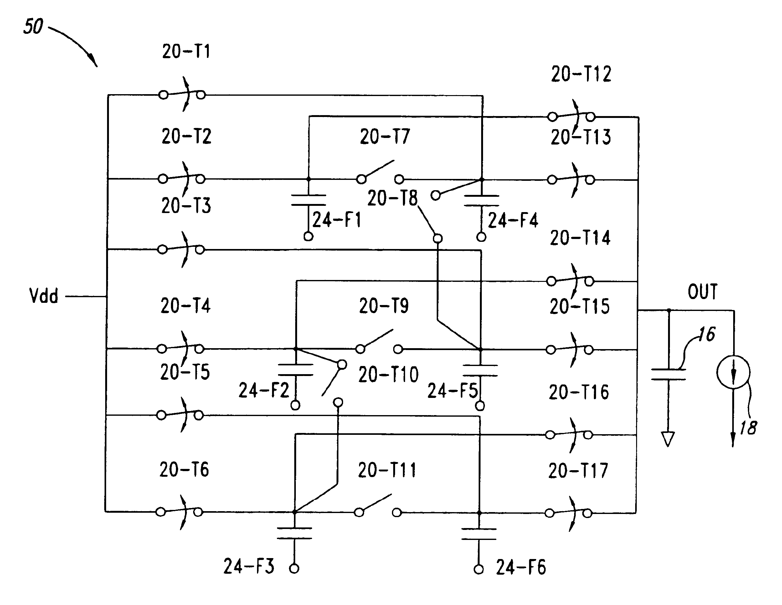
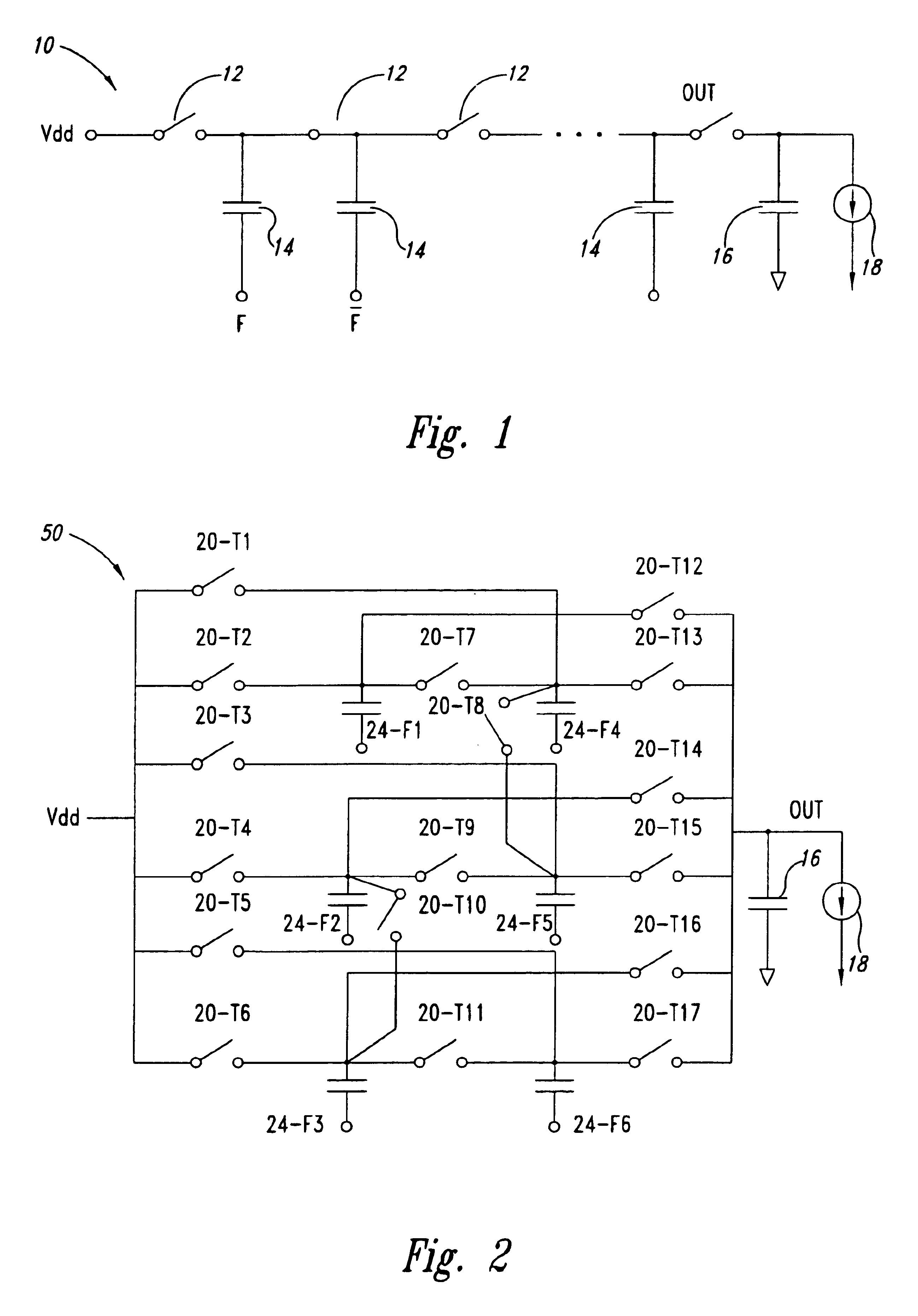
[0043]According to embodiments of the invention, a variable stage charge pump can be obtained by dividing the total capacitance, CTOT, from equations 1 and 2, into a suitable number of pumping capacitors, and connecting these pumping capacitors together through a suitable switching network. The switching network acts on the frequencies of the pumping capacitors and on the frequency of the switching drivers to decide the appropriate number of stages in the charge pump.

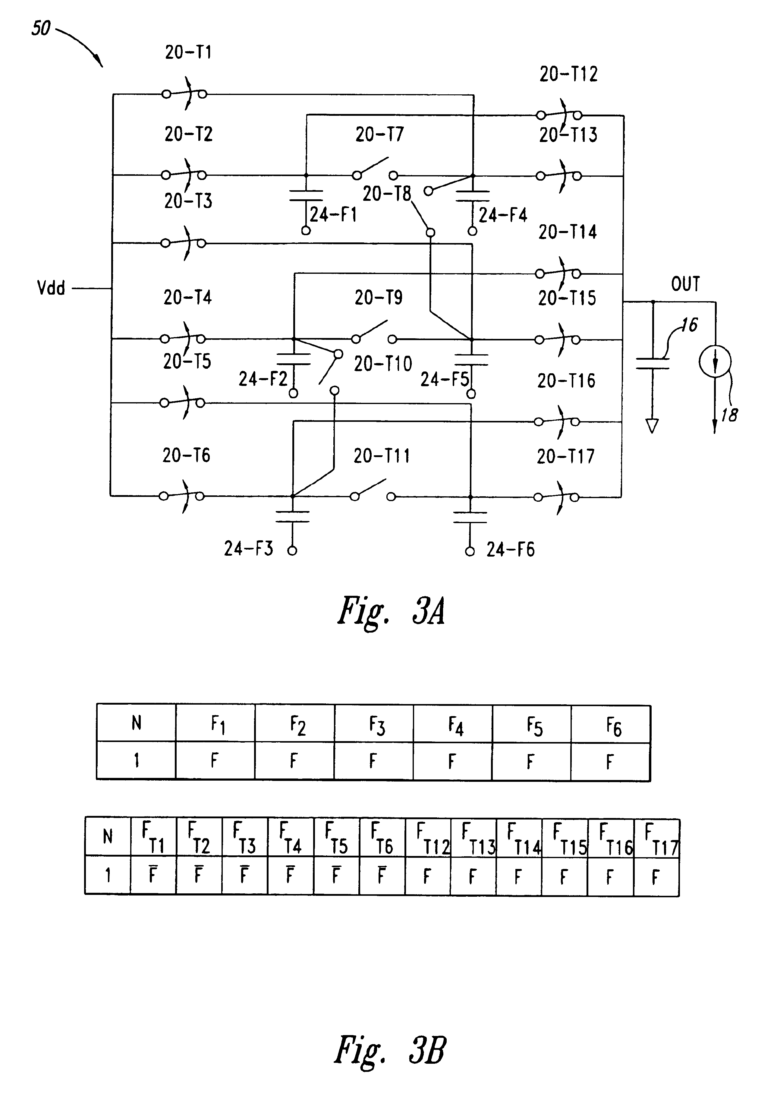
[0044]FIG. 2 is a schematic diagram of an example charge pump 50 according to an embodiment of the invention. The charge pump 50 includes between 1 and 3 stages, depending on a configuration of its switching network. The charge pump 50 includes a number of switches 20, individually labeled T1-T17, and a number of capacitors 24, individually labeled F1-F6. Each of the switches 20 is individually controllable to either an open or shut position, although they are all shown in FIG. 2 as being open. Also included in the char...


PUM


Abstract

A variable charge pump contains several individual simple charge pumps, each with a pumping capacitor and a switching mechanism. Additionally, a switching network is coupled to the individual charge pumps so that the different lines in the charge pump can be connected together in a serial mode or parallel mode (or mixed serial and parallel modes) to match the needs of the output load. The switching network is easily changed to provide the necessary driving capability as the needs of the output load changes.

Description

BACKGROUND OF THE INVENTION[0001]1. Field of the Invention[0002]The present invention relates to variable stage charge pumps, and, more specifically, to a charge pump that has a selectable number of stages.[0003]2. Description of the Related Art[0004]In some electronic devices, the power supply voltage is not high enough to guarantee the correct operation of the circuit. In these cases, higher voltages are required. For example, voltages up to 15 volts are needed for programming and erasing operations in a non-volatile memory device.[0005]When a voltage higher than the power supply voltage is required, a second power supply can be furnished from outside the circuit. Until a few years ago, this was the only solution available. Presently, the required voltages can be also generated inside the integrated circuit. On-circuit high voltage generation is now more widespread than off-chip generation, because of lower implementation cost.[0006]A circuit that can provide higher voltage values...

Claims


Application Information

Patent Timeline
IPC IPC(8): H02J7/00H02M3/07H02M3/04
CPCH02M3/07H02M2003/077H02M3/077
Inventor PAPPALARDO, DOMENICOGAIBOTTI, MAURIZIOPALUMBO, GAETANOCONTE, ANTONINOLO GIUDICE, STEFANO
Owner STMICROELECTRONICS SRL
Why Eureka
Try Eureka