Low loss reciprocating electromagnetic device

a reciprocating electromagnetic and low-loss technology, applied in the direction of dynamo-electric components, dynamo-electric machines, magnetic circuit shapes/forms/construction, etc., can solve the problems of thermal stability in operation, axially-laminated structures are not well adapted to mechanical load-bearing, and conductivity gives rise to losses called eddy currents, etc., to achieve better mechanical integrity, lower cost, and high efficiency

Inactive Publication Date: 2005-08-09
CHART INC
View PDF15 Cites 2 Cited by
  • Summary
  • Abstract
  • Description
  • Claims
  • Application Information

AI Technical Summary

Benefits of technology

[0014]A third aspect of the invention includes a method of reducing eddy-current losses in a region of three-dimensional magnetic flux orientation in an electromagnetic device having a moving element and a stationary element including layered laminates of magnetically-permeable material, the method comprising the steps of: shaping a pole interface between the moving element and the stationary element of the electromagnetic device to reduce local magnetic flux density; and providing an interruption in electrically-conductive paths in the planes of the laminated layers of the stationary element to reduce eddy currents.
[0017]The above aspects provide higher efficiency in economical, high-power electrodynamic reciprocators; lower cost and better mechanical integrity in high-efficiency electrodynamic reciprocators; enablement of many new markets and applications not previously addressable with resonator-type thermoacoustic and Stirling devices, where high efficiency at low cost is required for commercial application; and enablement of complex device geometries that require locally-complex three-dimensional magnetic flux fields, without suffering excessive eddy-current losses.

Problems solved by technology

Such conductivity gives rise to losses called eddy currents, by acting as closed, conductive circuits around changing magnetic flux vectors.
Although this approach generally aligns the laminate orientation to the magnetic flux vectors, it is costly and requires special manufacturing processes and equipment not shared with more common rotary machines.
Such axially-laminated structures are also not well adapted to mechanical load-bearing, attachment to other structures, or thermal stability in operation.
No such provisions are made in Nasar, which implies either a higher loss or a lower magnetic flux density throughout, and associated larger mass and cost.
Unfortunately, the losses in the pole area can dominate the total loss inventory, especially at higher frequencies.
At present, these insulated composites are very costly and such materials exhibit lower total permeability and magnetic saturation levels.
Still, they can be molded to shapes that cannot be laminated easily, and they carry magnetic flux in any direction without high eddy current losses because there are no large-scale conductive pathways in the material.

Method used


Image

  • Low loss reciprocating electromagnetic device
  • Low loss reciprocating electromagnetic device
  • Low loss reciprocating electromagnetic device

Examples


first embodiment

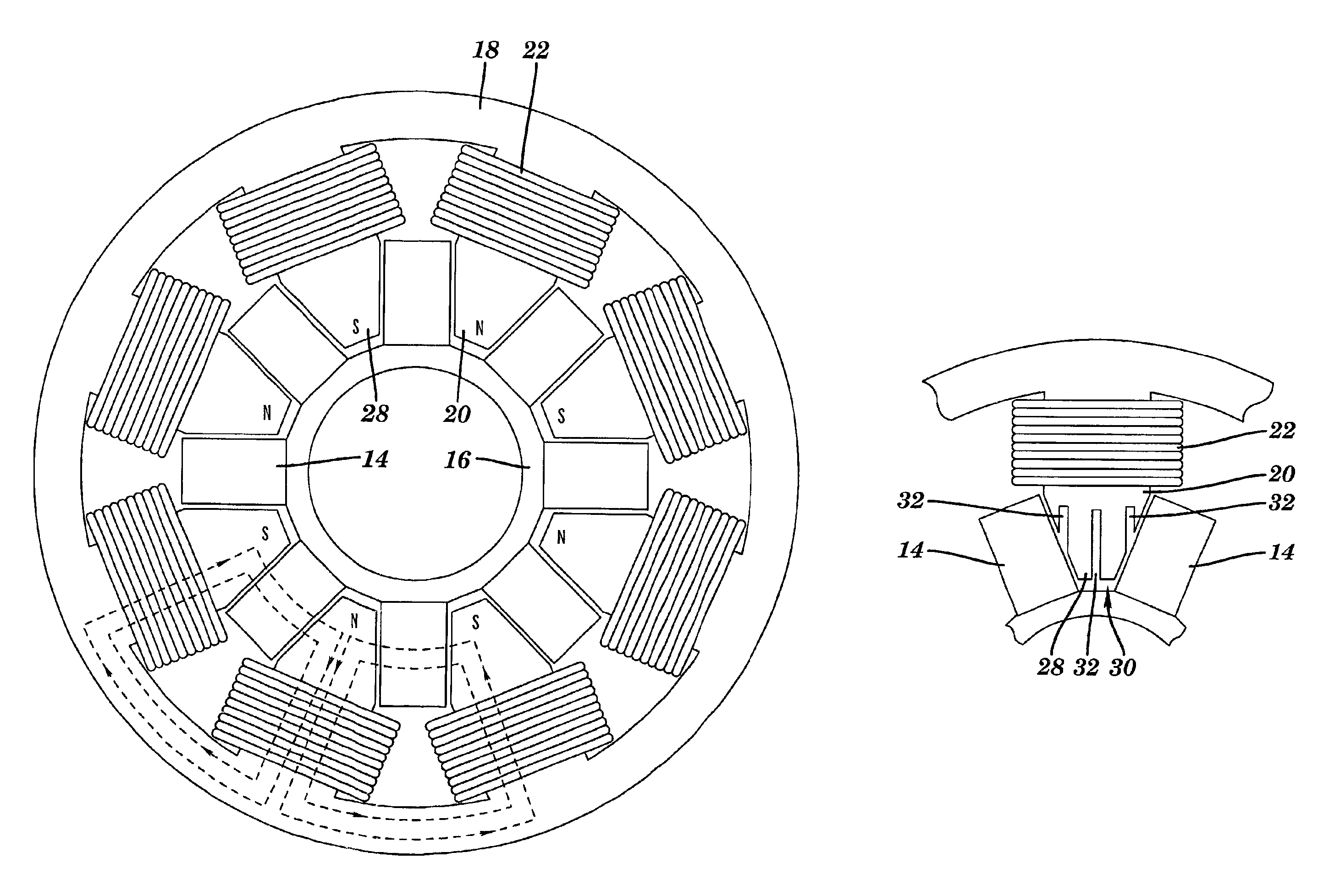
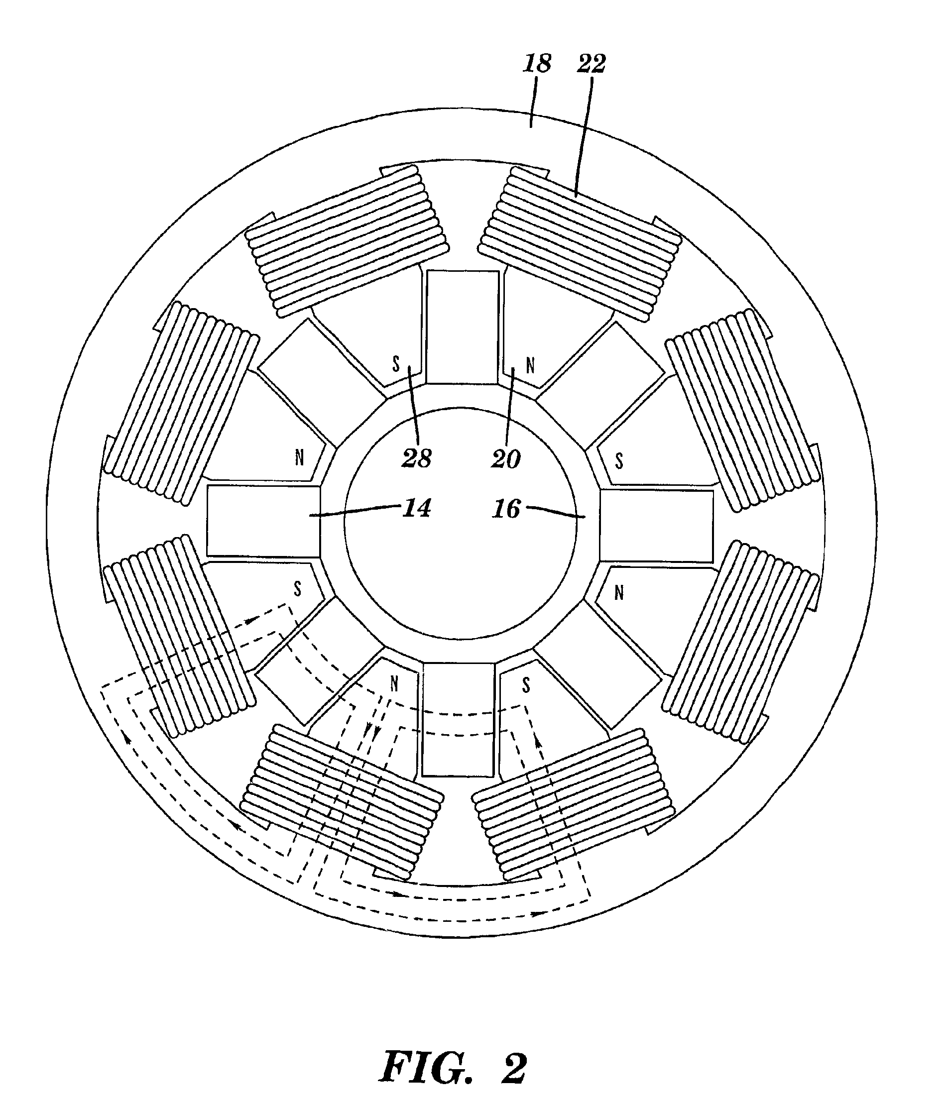
[0040]According to the invention shown in FIG. 9, the lower-flux density pole tip region 28 of the device includes one or more interruptions. By “interruptions” is meant a discontinuity in the local electrical conductance of the magnetically-permeable material. One way of providing interruptions is by placing voids 30 in the pole 20. One mechanism for providing these voids 30 is by placing one or more slots 32 in the pole 20. Slots 32 preferably are substantially perpendicular to the laminations (themselves perpendicular to the reciprocation axis), and substantially aligned to the desired magnetic flux paths through the slotted part of the layered laminates. Of course, other voids 30 may be implemented depending on the desired routing of magnetic flux in the layered laminates. The reduction in eddy current losses have been calculated, based on some simplifying assumptions. In particular, the drag force resulting from eddy currents in the roughly-triangular pole tips 20 of a transver...

second embodiment

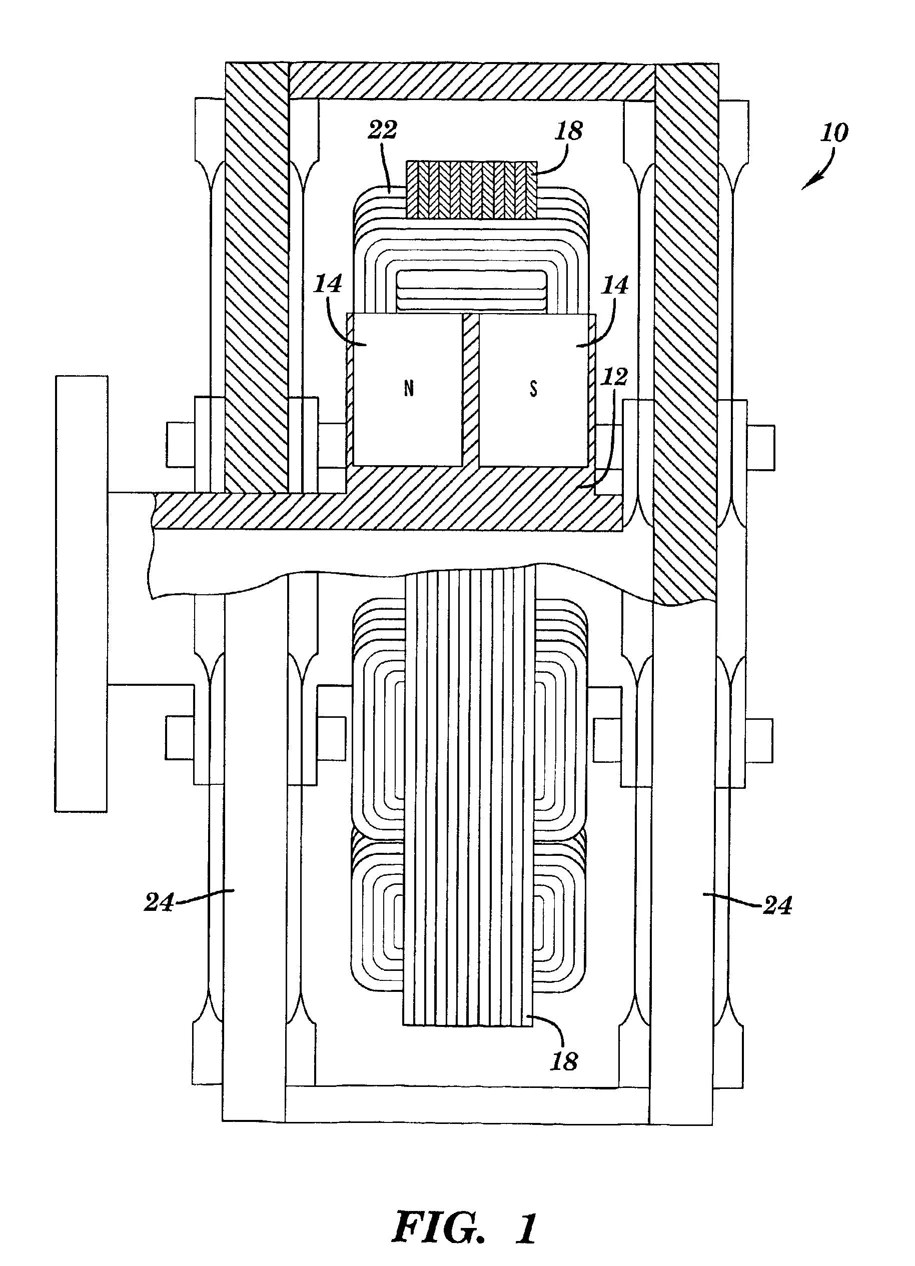
[0043]Referring to FIG. 10, according to the invention, the pole tip region where magnetic flux is not aligned well to the laminations and where magnetic flux density may be held lower than otherwise desirable in other parts of the stationary element (e.g., under the coils, to minimize resistive loss and iron mass), is replaced by a separate piece, formed from an insulated magnetically-permeable composite part 36 to provide an interruption. Such materials consist of small particles of iron or other magnetically-permeable material, separated and bonded by an electrically-insulating material, typically a polymer. An example is ANCORSTEEL by Hogaenes Corp. FIG. 10 shows such an adaptation on the device of FIG. 1, in which the formed composite part 36 also serves as a retainer for coil / winding 22. The interface between the insulated part and the laminations is sized and shaped into a keyed contact 37 that locates composite part 36 on the laminates of pole 20 and provides a transition ar...


PUM


Abstract

The present invention relates generally to reciprocating electromagnetic devices, and more particularly to a construction of a reciprocating electromagnetic device for reducing secondary losses in magnetically-permeable elements, but without compromising manufacturability as required in prior art. The device provides for shaped pole faces to reduce local magnetic flux density and / or interruptions of electrically-conductive paths in the planes of the laminated layers of the stationary element of the device.

Description

REFERENCE TO PRIOR APPLICATION[0001]The current application claims priority to co-pending provisional application Ser. No. 60 / 324,842, filed on Sep. 25, 2001 and incorporated herein by reference.BACKGROUND OF THE INVENTION[0002]1. Technical Field[0003]The present invention relates generally to reciprocating electromagnetic devices, and more particularly to a construction of a reciprocating electromagnetic device for reducing secondary losses in magnetically-permeable elements.[0004]2. Related Art[0005]Direct conversion of AC electric power into reciprocating mechanical power by resonant motors (and the reverse conversion in alternators) has become important in applications like pulse-tube and Stirling-cycle cryocoolers and small externally-heated engine-generators operating on a thermoacoustic or Stirling cycle. As with rotary motors and alternators, these devices typically include a moving field (permanent or electromagnet) interacting with a fixed field, typically electrically-con...

Claims


Application Information

Patent Timeline
Patent Type & Authority Patents(United States)
IPC IPC(8): H02K1/06H02K35/02H02K35/00H02K33/00H02K1/34H02K33/16
CPCH02K1/34H02K33/16H02K35/02
Inventor COREY, JOHN A.
Owner CHART INC
Why Eureka
Try Eureka