Piezoactive actuator with dampened amplified movement

a technology of amplified movement and actuator, which is applied in piezoelectric/electrostrictive/magnetostrictive devices, piezoelectric/electrostriction/magnetostriction machines, electrical apparatus, etc. it can solve the problems of insufficient mechanical damping capacity, insufficient resistance to dynamic external forces, and all the deformation of actuators to be recovered, so as to achieve the effect of dampening the vibration of the structur

Active Publication Date: 2005-08-09
CEDRAT TECH
View PDF14 Cites 66 Cited by
  • Summary
  • Abstract
  • Description
  • Claims
  • Application Information

AI Technical Summary

Benefits of technology

[0031]The actuator can be arranged so as to dampen vibrations of a structure to which it is fixed.

Problems solved by technology

This mode of use of the actuator requiring a central actuating point is constraining as it is not compatible with the previous one and does not enable all the deformation of the actuator to be recovered.
Amplified piezoelectric actuators can cause the problem of an insufficient resistance to dynamic external stresses and of an insufficient mechanical damping capacity.
Amplified piezoelectric actuators do in fact sometimes show large quality factors: they can limit the resistance of the actuators under external dynamic stresses.
A direct piezoactive actuator preloaded by means of one of the foregoing means and placed inside the mechanical amplifier presents two drawbacks:the mechanical link between the preloaded direct piezoactive actuator and the mechanical amplifier has to withstand a high traction force equal to the preloading stress and leads to a bulky connection,this solution is hardly compatible with the possibility of controlling the degree of freedom in translation of the amplified piezoactive actuator.
However, the cable stays are difficult to master, especially in small dimensions.

Method used


Image

  • Piezoactive actuator with dampened amplified movement
  • Piezoactive actuator with dampened amplified movement
  • Piezoactive actuator with dampened amplified movement

Examples


Embodiment Construction

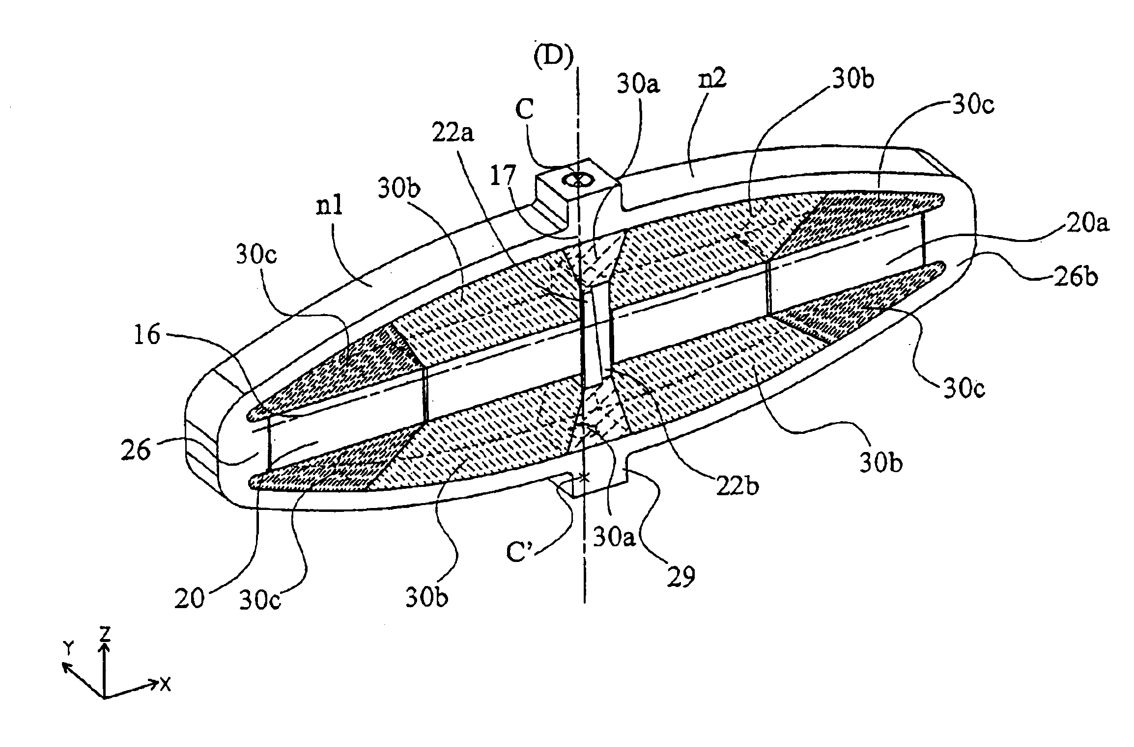
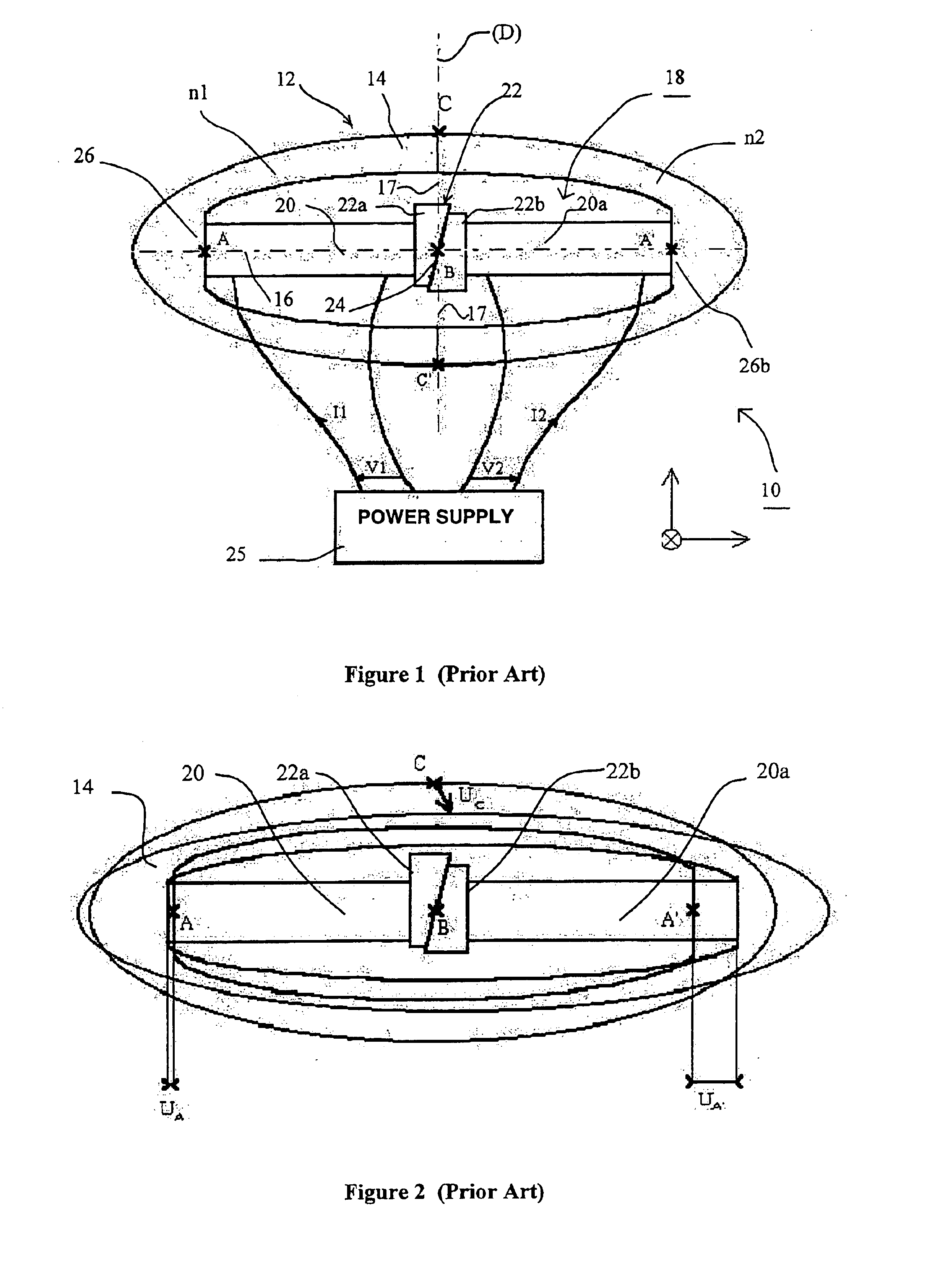
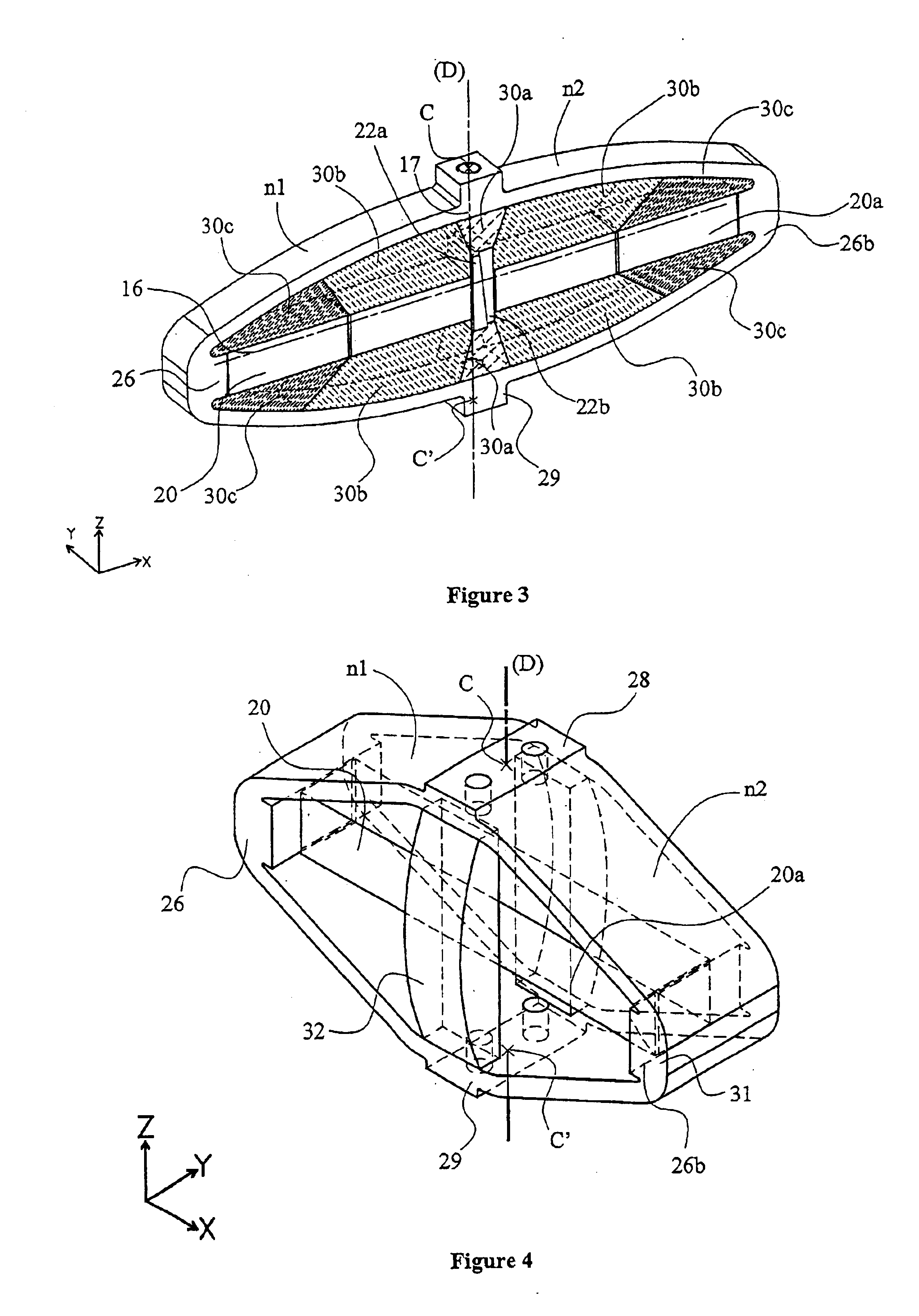
[0045]With reference to FIG. 1, the piezoactive actuator 10 comprises a first sub-assembly formed by a mechanical movement amplifier 14 arranged as a shell with two branches n1 and n2, each branch being approximately semi-elliptic, for example in the form of a symmetrical basket-handle. The mechanical amplifier 14 is formed by one or more deformable flexible materials, for example steel, aluminum or titanium alloy or a composite material, and is not provided with thinning zones.

[0046]The elliptic shell of the mechanical amplifier 14 has a large axis 16 extending in the x direction, and a small axis 17 perpendicular to the large axis 16 and extending in the z direction.

[0047]The second sub-assembly 18 includes piezoactive elements 20, 20a and possibly a clearance take-up device 22, arranged jointly inside the mechanical amplifier 14.

[0048]The piezoactive elements 20, 20a are formed by straight rods aligned in the direction of the large axis 16 inside the shell and able to be subjecte...


PUM


Abstract

The piezoactive actuator with amplified movement comprises a first sub-assembly formed by a mechanical movement amplifier and a second sub-assembly equipped with piezoactive elements. An interface with a load and an interface with a base, respectively placed at the peaks of a small axis of the shell and designed for actuating the load with respect to the base, define an actuating axis. A longitudinal deformation of the large axis enables a deformation of the small axis to be induced, designed to generate a movement at the interface with the load, the component of which movement along the small axis is amplified. At least one zone made of elastomer material is arranged at least substantially along the actuating axis to dampen deformations and increase the capacity of the actuator to resist external stresses. The actuator comprises at least one free space adjacent to the elastomer material zones in a direction orthogonal to the actuating axis.

Description

BACKGROUND OF THE INVENTION[0001]The invention relates to a piezoactive actuator with amplified movement comprising:[0002]a first sub-assembly formed by a mechanical movement amplifier arranged as a shell with at least two branches made of deformable flexible material, having a large axis and a small axis extending perpendicularly to one another, an interface with a load and an interface with a base, respectively placed at the peaks of the small axis of the shell and designed for actuating the load with respect to the base, defining an actuating axis,[0003]a second sub-assembly equipped with linear piezoactive elements mounted inside the shell in the direction of the large axis and electrically excited by a power supply circuit to produce a longitudinal deformation of the large axis and to induce a deformation of the small axis designed to generate at the interface with the load a movement the component whereof along the small axis is amplified.STATE OF THE ART[0004]A piezoactive ac...

Claims


Application Information

Patent Timeline
Patent Type & Authority Patents(United States)
IPC IPC(8): H01L41/09H02N2/02H02N2/04
CPCH02N2/0095H02N2/028H02N2/043
Inventor BARILLOT, FRANÇOISCLAEYSSEN, FRANKLE LETTY, RONAN
Owner CEDRAT TECH
Why Eureka
Try Eureka