
Electron gun and color picture tube apparatus that attain a high degree of resolution over the entire screen

a color picture tube and color gun technology, applied in the direction of lighting and heating apparatus, cathode ray tubes/electron beam tubes, semiconductor devices for light sources, etc., can solve the problems of difficult to make a difference between horizontal and vertical convergence power of the main lens, complex lens design, etc., to reduce spherical aberration, reduce the effect of phosphor screen phosphor aberration, the aperture of each lens can be increased

Inactive Publication Date: 2005-08-09
PANASONIC CORP
View PDF7 Cites 0 Cited by
  • Summary
  • Abstract
  • Description
  • Claims
  • Application Information

AI Technical Summary

Benefits of technology

"The present invention provides an electron gun and a color picture tube apparatus that can easily supplement the reduced HV differential, without electron beam mislanding. The apparatus includes a panel that has a phosphor screen and an electron gun that emits a plurality of electron beams towards the phosphor screen. The electron gun includes a plurality of cathodes, a pair of main lens-generating tube-shaped electrodes, and a pair of quadrupole lens-generating electrodes. The main lens is generated by the two opposing tube-shaped electrodes, which each have an internal correction electrode. The quadrupole lens formed on the screen side of the main lens has a convergent action in the horizontal direction and a divergent action in the vertical direction, allowing for optimal focusing and high resolution over the whole screen. The static convergence of the electron beams can be adjusted by the quadrupole lens provided on the screen-side, eliminating the need to widen the gap between the screen and the shadow mask and preventing mislanding caused by geomagnetism."

Problems solved by technology

This problem has been accentuated in recent years as panels become flatter and deflection angles increase.
However, the following two problems arise when the main lens is an OLF lens.
The first problem is that it is difficult make the convergence power of the main lens different in the horizontal and vertical directions.
Consequently, a problem with OLF lenses is that the lens design is complicated compared to a conventional electron gun main lens.
When design of the electric field lens is so difficult, it is difficult to make a difference between horizontal and vertical convergence power of the main lens (hereinafter referred to as the “HV differential”), and the design of the HV differential of the main lens becomes limited.
As a result, aligning the diameters of the electron beams in the horizontal and the vertical directions difficult, and there is little significance to the increased aperture size of the main lens that has been provided to the improve resolution.
However, as described above, in an OLF lens design difficulties make it is hard to attain the desired HV differential, and this technique is difficult to realize.
The second problem is the occurrence of mislanding which causes color discrepancy.
However, if the gap Q is increased in this way, geomagnetism between the screen 205 and the shadow mask 207 mis-aligns the trajectories of the electron beams, thus causing color discrepancies, and deterioration in resolution in the outer parts of the screen.

Method used


Image

  • Electron gun and color picture tube apparatus that attain a high degree of resolution over the entire screen
  • Electron gun and color picture tube apparatus that attain a high degree of resolution over the entire screen
  • Electron gun and color picture tube apparatus that attain a high degree of resolution over the entire screen

Examples


first embodiment

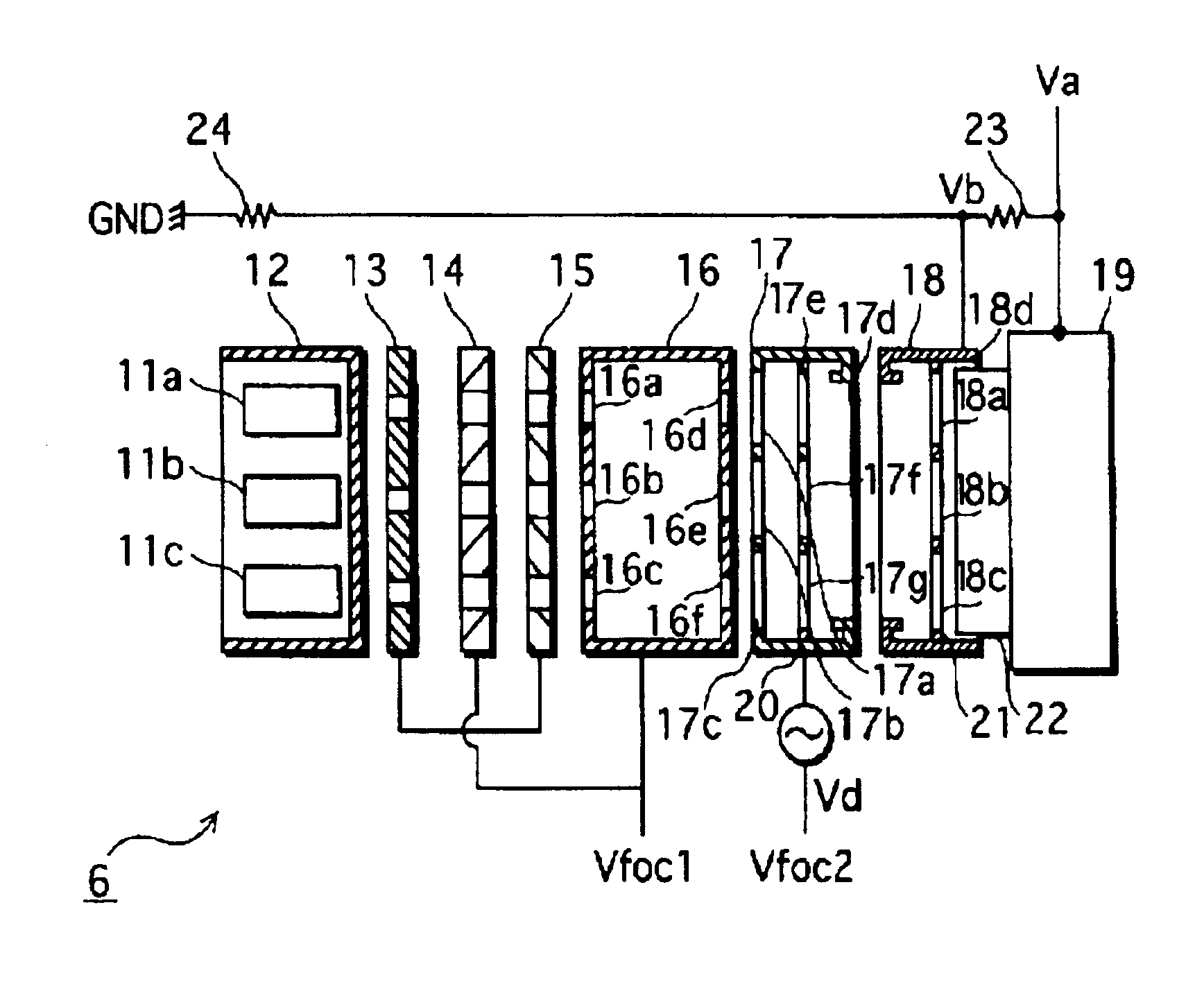
[0052]FIG. 4 is a perspective diagram showing the structure of an inline electron gun in a first embodiment partially cut away, and FIG. 5 is a cross-sectional diagram of the electron gun 6 of FIG. 4 seen from a vertical direction.

[0053]As these drawings show, the electron gun 6 includes a set of three cathodes 11a, 11b and 11c provided inline (see FIG. 5), and, provided successively, a control electrode 12 that houses the cathodes 11a, 11b and 11c, an accelerating electrode 13, a first focus electrode 14, a second focus electrode 15, a third focus electrode 16, a fourth focus electrode 17, a final accelerating electrode 18 and a shield cup 19. These electrodes are supported by an insulated frame (not illustrated) in order to preserve their mutual positional relationship.

[0054]The control electrode 12, the accelerating electrode 13, the first focus electrode 14 and the second focus electrode 15 are each provided with three substantially round electron-beam through-holes that corresp...

second embodiment

[0088]The following describes an electron gun in the present invention.

[0089]The electron gun of the present embodiment generates, in the same manner as the electron gun of the first embodiment, a first quadrupole lens that on the cathode side of the main lens and that has a divergent action in the horizontal direction and a convergent action in the vertical direction, and also generates a second quadrupole lens that is on the screen side of the main lens and that has a convergent action in the horizontal direction and a divergent action in the vertical direction.

[0090]In contrast to the electron gun 6 in which, as shown in FIGS. 5 and 8, the shield cup 19 that has the screen-shaped electrodes and the final accelerating electrode 18 generate the second quadrupole lens, in the present embodiment, the second quadrupole lens is generated, as shown in FIG. 10, by the final accelerating electrode 18 that has a plate electrode 41 provided on the shield cup electrode 19 side, and the shiel...

third embodiment

[0103]The following describes an electron gun 60 in the present invention.

[0104]FIG. 13 is a schematic cross-sectional diagram of the electron gun 60 in the third embodiment. Components in the present embodiment have the same reference numerals as the first embodiment shown in FIG. 5 are the same thereas, and are therefore not described here. The voltages and resistance values of the resistors are the same as the electron gun 6.

[0105]As shown in FIG. 13, the electron gun 60 in the present embodiment differs from the electron gun 6 in the first embodiment in that a tube-shaped intermediate electrode 61 is provided between the fourth focus electrode 17 and the final accelerating electrode 18.

[0106]The intermediate electrode 61 has one opening on each of a fourth focus electrode 17 side and a final accelerating electrode 18 side. A plate-shaped correction electrode 62 is provided in a central part of the intermediate electrode 61. The correction electrode 62 has three non-circular elec...


PUM


Abstract

A set of three cathodes, a control electrode, an accelerating electrode, a first focus electrode, a second focus electrode, a third focus electrode, a fourth focus electrode, a final accelerating electrode and a shield cup electrode are provided successively in an electron beam travelling direction. The shield cup electrode has a pair of screen-shaped electrodes that sandwich electron-beam through-holes in a vertical direction. A quadrupole lens that has a horizontal convergent action and a vertical divergent action is generated by an electrical potential difference between the screen-shaped electrodes and the final accelerating electrode. Accordingly, even if vertical and horizontal convergence power difference in a main lens formed by the fourth focus electrode and the final accelerating electrode is not large, a composite lens formed through a combination of the quadrupole lens and the main lens has strong horizontal convergence power and weak vertical convergence power.

Description

BACKGROUND OF THE INVENTION[0001](1) Field of the Invention[0002]The present invention relates to an electron gun that is structured so as to attain a high degree of resolution over the entire screen, and a color picture tube apparatus that includes the electron gun.[0003](2) Related Art[0004]Generally, a color picture tube apparatus has an envelope formed from a panel and a funnel joined to the panel, and displays color images by emitting three electron beams from an electron gun disposed in a neck of the funnel, onto a phosphor screen formed opposite a shadow mask on an inner surface of the panel, while scanning horizontally and vertically. The three electron beams are deflected by horizontal and vertical deflection magnetic fields generated by a deflection device mounted to the outside of the funnel.[0005]The magnetic fields generated by the deflection device used in the above color picture tube apparatus generally have a self-convergence structure to focus the three electron bea...

Claims


Application Information

Patent Timeline
Patent Type & Authority Patents(United States)
IPC IPC(8): H01J29/50H01J29/48
CPCH01J29/503F21V23/003F21V23/001F21V17/101F21Y2115/10
Inventor UEDA, YASUYUKISUKENO, MASAHIKO
Owner PANASONIC CORP
Learn More