Magnetic resonance apparatus including an rf magnetic flux guiding structure for improving the signal-to-noise ratio

Inactive Publication Date: 2005-08-09
KONINKLIJKE PHILIPS ELECTRONICS NV
View PDF19 Cites 16 Cited by
  • Summary
  • Abstract
  • Description
  • Claims
  • Application Information

AI Technical Summary

Benefits of technology

[0015]The structure enables the receive coil to be stood off from the surface of the object being exam

Problems solved by technology

Much of that noise comes from regions closest to the coil windings, which contribute a disproportionate amount relative to the value of the data obtained from them.
The disadvantage of this is an increase in noise from the regions of the body adjacent to the coil.
Because of the ref

Method used


Image

  • Magnetic resonance apparatus including an rf magnetic flux guiding structure for improving the signal-to-noise ratio
  • Magnetic resonance apparatus including an rf magnetic flux guiding structure for improving the signal-to-noise ratio
  • Magnetic resonance apparatus including an rf magnetic flux guiding structure for improving the signal-to-noise ratio

Examples


example

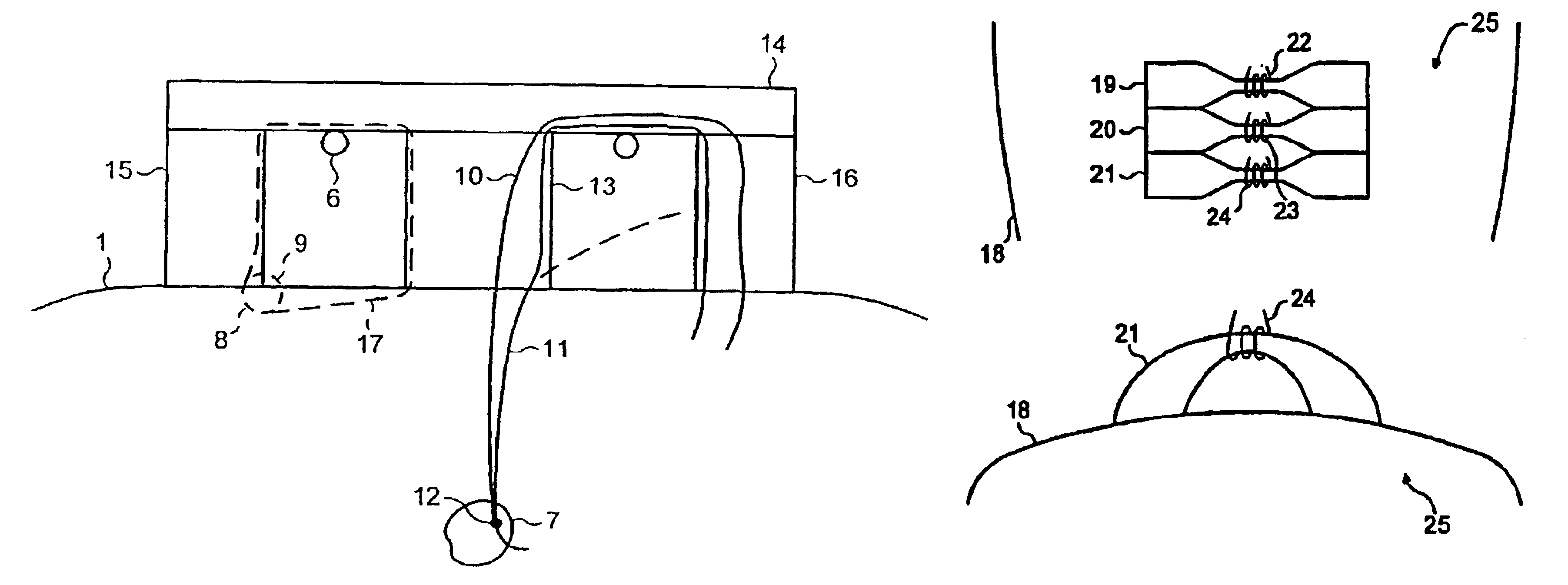
[0049]In one example of roll material, the material consists of cylindrical elements, with each cylinder being a “Swiss Roll”. They are made of 37 turns of film, wound on a 8 mm diameter, non-magnetic core (a glass-reinforced plastic, GRP, rod). The film is a proprietary material, known as ProFilm (Trade Mark), which consists of a Mylar (Trade Mark) base, coated with about 10 nm of aluminium and a glue layer, the whole being approximately 50 μm thick. The sheet resistance of the aluminium layer is about 2.7 Ω / square. The outer diameter of the cylinders is 11.4 mm, and the material is assembled in a hexagonal close packed lattice (i.e. as closely packed as possible). This construction provides a maximum permeability of μ=3 at 21.3 MHz and a permeability of air at other frequencies and steady state fields.

[0050]In another example, an alternative film is provided by the so-called “Superinsulation” (Trade Mark) used in superconducting magnet systems. This is a Mylar (Trade Mark) film of...


PUM


Abstract

A pad which has a magnetic permeability greater than that of free space at the frequency of nuclear magnetic resonance but which is non-magnetic in steady magnetic fields is disposed between an RF coil and the surface of a patient. The pad is surmounted by a block having similar properties. Two further pads extend from the ends of the block to the surface of the patient. The pads and block guide magnetic flux, which is indicative of magnetic resonant active nuclei in the patient, towards an RF coil which is spaced apart from the surface of the patient/object under examination.

Description

BACKGROUND OF THE INVENTION[0001]This invention relates to signal-to-noise ratio improvement in magnetic resonance apparatus, such as magnetic resonance imaging apparatus or magnetic resonance spectroscopy apparatus.[0002]A typical magnetic resonance imaging apparatus is shown in FIG. 1. A patient 1 on a couch 2 is slid into the bore 3 of an annular electromagnet, typically a superconducting electromagnet. A main magnetic field is generated in alignment with the axis of the bore, and gradient coils (not shown) are provided to set up magnetic field gradients for example along the z-direction along the axis of the bore, and along x and y directions in the radial plane. A transmit coil 4 surrounds the patient and transmits pulses of r.f. energy to excite to resonance magnetic resonance active nuclei such as protons in the region of the patient to be examined. This transmit coil 4 is normally surrounded by an r.f. shield coil 5 to shield the bore 3 of the electromagnet from extraneous u...

Claims


Application Information

Patent Timeline
IPC IPC(8): G01R33/32G01R33/56G01R33/54G01R33/34A61B5/055H01F5/00
CPCG01R33/32G01R33/34015G01R33/34023G01R33/341
Inventor YOUNG, ROBERT IANWILTSHIRE, MICHAEL CHARLES KEOGH
Owner KONINKLIJKE PHILIPS ELECTRONICS NV
Why Eureka
Try Eureka