Optical transmission module

a transmission module and optical technology, applied in the direction of waveguide type devices, coupling device connections, instruments, etc., can solve the problems of affecting the transmission efficiency of high frequency signals, and difficult to realize the connection of such external conductors with ground electrodes of coplanar transmission lines. , to achieve the effect of no mechanical damage, no interfering electromagnetic wave radiation, and excellent high frequency characteristics

Inactive Publication Date: 2005-08-09
LUMENTUM JAPAN INC
View PDF4 Cites 18 Cited by
  • Summary
  • Abstract
  • Description
  • Claims
  • Application Information

AI Technical Summary

Benefits of technology

[0018]According to the present invention, a thin and small size optical transmission module connected to a coaxial cable which assures less radiation of interfering electromagnetic wave, excellent high frequency characteristic and no-generation of mechanical damage can be attained by providing an electromagnetic field mode alleviating portion of a dielectric material to the core wire part of the coaxial cable without use of a connector for connection.

Problems solved by technology

Therefore, this bonding wire is not suitable for transmission of a high frequency signal.
Extreme change of the direction of electromagnetic field causes degradation of transmission efficiency of an high frequency signal.
Moreover, since the thin external conductor of a coaxial cable is spreading in the circumferential area of the signal wire, it has been difficult to realize the connection of such external conductor with a ground electrode of the coplanar transmission line substrate.
As a result of actual connection using such contact sleeve, it has been proved that when the contact sleeve is formed thinner, poor connection is easily generated in the solder connection to the ground electrode of a coplanar transmission line.
It has also become obvious that if such poor connection is generated, a signal wire as the core wire of a coaxial cable is no longer covered with an external conductor at a certain area and a fine potential difference is generated in the ground potential of a ground wire between the contact sleeve and the coplanar transmission line.

Method used


Image

  • Optical transmission module
  • Optical transmission module
  • Optical transmission module

Examples


embodiment 1

[Embodiment 1]

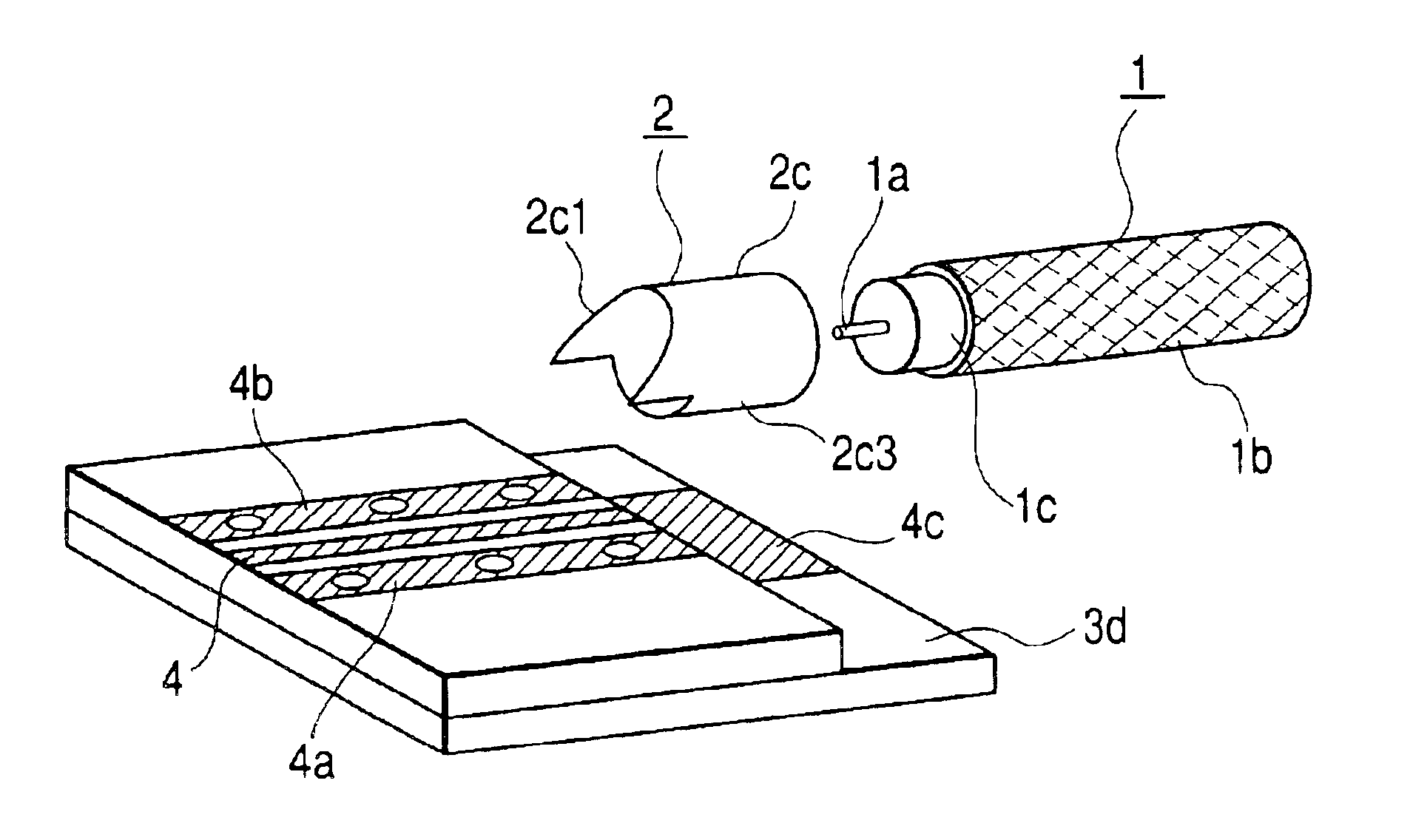
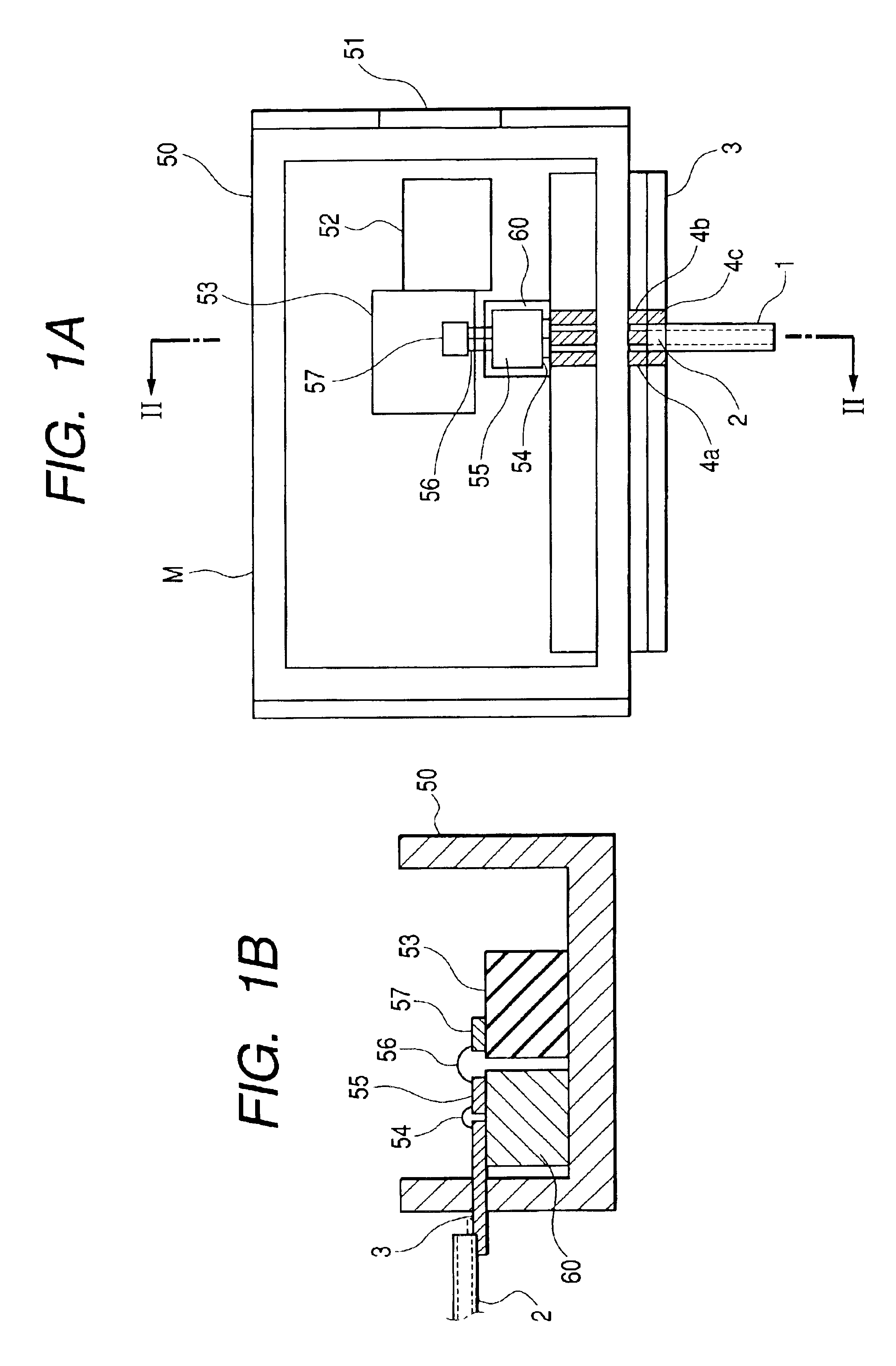
[0031]The embodiment 1 and its modification example of an optical transmission module to achieve the first object will be explained with reference to the drawings of FIG. 1 to FIG. 6. In FIGS. 1A and 1B, a housing 50 of the optical transmission module M is provided at its interior with a metal block 53 placing a lens 52 coupled with an optical output 51 provided to one of the short-end portions. An optical element 57 is placed on the metal block 53. Meanwhile, a ceramic grounded coplanar line substrate 3 is loaded to one of the long-end portions at the housing 50 of the optical transmission module M.

[0032]The ceramic grounded coplanar line substrate 3 has a grounded coplanar structure. This grounded coplanar line structure will be explained later with reference to FIG. 2. The grounded coplanar line substrate 3 of ceramic is provided with a signal electrode 4 and ground electrodes 4a, 4b, 4c which are connected with a coaxial cable 1 for transmitting a high frequency si...

embodiment 2

[Embodiment 2]

[0072]Although detail illustration is omitted here, the other modification example of the connection between a transmission line substrate and a coaxial cable in the optical transmission module of the present invention will be explained.

[0073]When a core line 1a of the coaxial cable 1 is connected to a signal electrode 4 of a grounded coplanar line 3a of the first layer, the positional alignment in the height direction is required from view point of control of radiation of electromagnetic wave. In this case, since the coaxial cable 1 is lower than the metal member or the second layer of the ground substrate, a spacer must be disposed to the bottom part of the coaxial cable 1.

[0074]Therefore, a projected portion is formed, in place of the spacer, so that the second layer consisting of the metal member or the ground substrate is projected in the extending direction of the coaxial cable more than the first layer including the grounded coplanar line formed on the second la...

embodiment 3

[Embodiment 3]

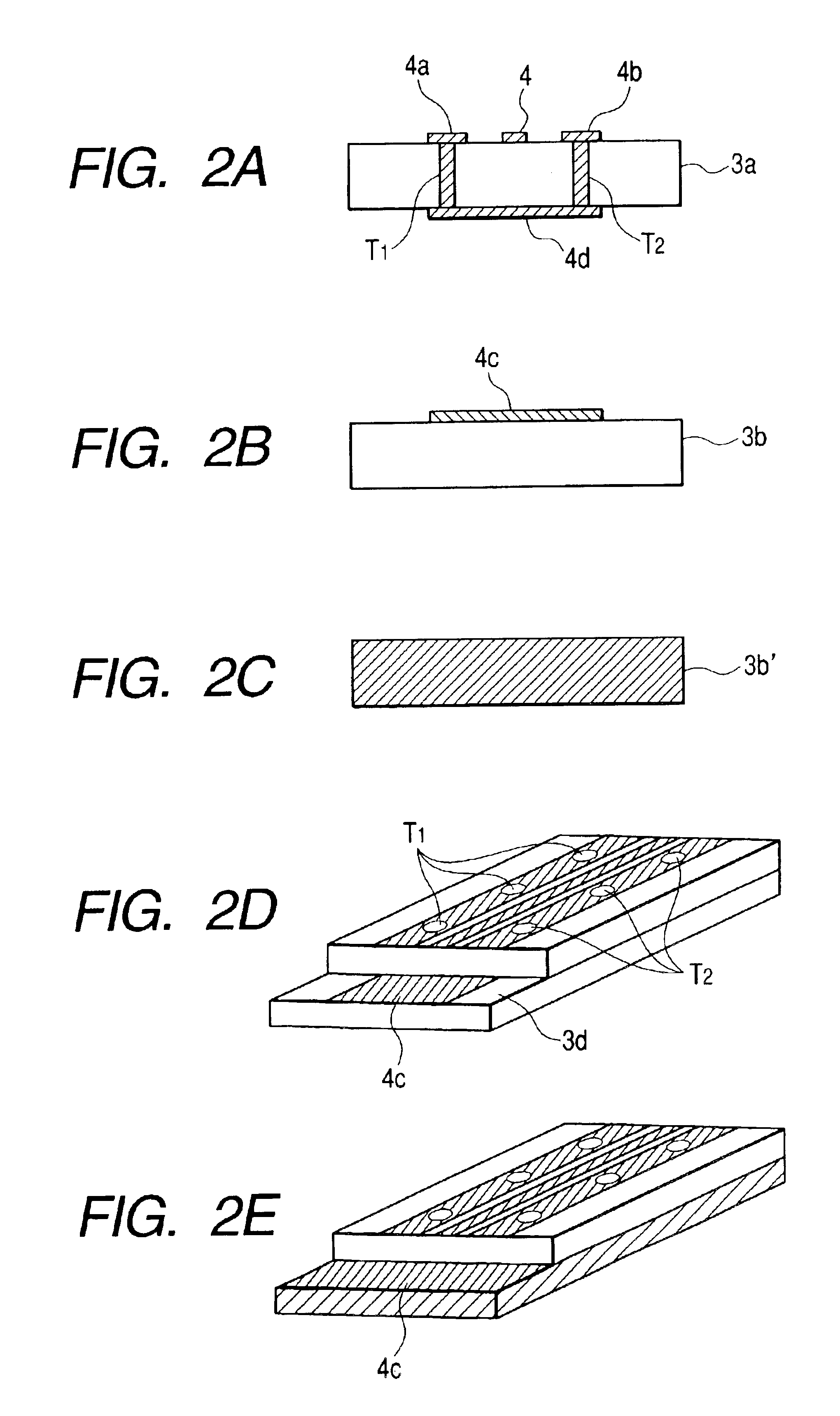
[0075]With reference to FIG. 7, a connecting portion between a transmission line substrate of the optical transmission module to attain the second object and a coaxial cable will be explained. FIGS. 7A and 7B illustrate the other connection example between the transmission line substrate of the optical transmission module of FIGS. 1A and 1B and a coaxial cable. In FIGS. 7A and 7B, the like elements having the identical specifications and functions as those in FIGS. 2A to 2E are designated with the like reference numerals, and the same explanation is not repeated here. FIG. 7A illustrates a connection between the transmission line substrate in the optical transmission module of FIGS. 1A and 1B and a coaxial cable, while FIG. 7B is a cross-sectional view taken along the line B-B′ after the connection of FIG. 7A.

[0076]In FIG. 7A, the transmission line substrate 3 is structured in the same manner as FIGS. 2A to 2E in the upper substrate 3a of the first layer and the transm...


PUM


Abstract

There is provided a thin and small size connector-less optical transmission module M which assures excellent high frequency characteristic. This optical transmission module comprises transmission line substrates and a coaxial cable for connecting these transmission line substrates and is connected to the transmission line substrate via a contact sleeve which is provided with projections fixed to the external conductor of the coaxial cable and projected in the extending direction of the coaxial cable. Since an electromagnetic field mode alleviating portion formed of a dielectric material is provided to the core wire of the coaxial cable, the thin and small size optical transmission module M can assure less amount of radiation of an interference electromagnetic wave, high frequency characteristic through connection with the coaxial cable.

Description

BACKGROUND OF THE INVENTION[0001]1. Field of the Invention[0002]The present invention relates to an optical transmission module and particularly to an optical transmission module in which a connection method of a high frequency transmission cable is utilized.[0003]2. Related Background Art[0004]An optical transmission module includes components mounted on different circuit boards. These components are connected with a bonding wire or a coaxial cable.[0005]When these components are connected with a bonding wire, an inductance increases according to the length of the bonding wire (connection distance). Therefore, this bonding wire is not suitable for transmission of a high frequency signal.[0006]Meanwhile, since a coaxial cable is covered with an external conductor, when the connection distance becomes longer, an inductance does not become larger than that of a bonding wire. Therefore, connection by a coaxial cable is suitable for transmission of a high frequency signal.[0007]In the c...

Claims


Application Information

Patent Timeline
Patent Type & Authority Patents(United States)
IPC IPC(8): G02B6/42H01R9/05H05K1/02H05K3/34H01L23/66
CPCG02B6/4201H01L23/66H01L2223/6627H01L2924/19033H01R9/0515H01R24/50H05K1/0219H05K3/3405H01L2224/48091H01L2224/48137H01L2924/00014
Inventor TORIGOE, MAKOTOSUGA, TAKASHI
Owner LUMENTUM JAPAN INC
Why Eureka
Try Eureka