Composite antenna

a technology of composite antennas and antennas, applied in the direction of resonant antennas, substantially flat resonant elements, independent non-interacting antenna combinations, etc., can solve the problems of complex work involved in mounting a plurality of antennas, and achieve the effect of reducing the mounting area, inhibiting the mutual influence of antennae, and facilitating handling

Inactive Publication Date: 2005-08-09
HARADA IND CO LTD
View PDF8 Cites 18 Cited by
  • Summary
  • Abstract
  • Description
  • Claims
  • Application Information

AI Technical Summary

Benefits of technology

[0022]According to the present invention which is thus constituted, because a loop antenna which operates in a second frequency band is formed on a dielectric substrate so as to surround a patch antenna which operates in a first frequency band, a small composite antenna which operates in two different frequency bands can be obtained. Accordingly, because, according to the present invention, a space in the loop antenna which operates in the second frequency band is used to form a patch antenna which operates in the first frequency band, a small composite antenna can be obtained, and the mount area thereof can be reduced and handling thereof facilitated.
[0023]Further, because the loop antenna and the patch antenna are provided on substantially the same axis, it is possible to inhibit the mutual influence of the antennae. In addition, when the patch antenna is provided with degeneracy isolation elements, a DSRC circularly polarized antenna for ETC and the like can be implemented, and, by providing the loop antenna with perturbation elements to constitute a circularly polarized antenna, a GPS antenna can be produced.

Problems solved by technology

There is therefore the problem that a plurality of antennae is required, same occupying a broad mount area, and the work involved in mounting a plurality of antennae is complicated.

Method used


Image

  • Composite antenna
  • Composite antenna
  • Composite antenna

Examples


first embodiment

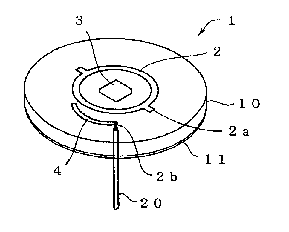
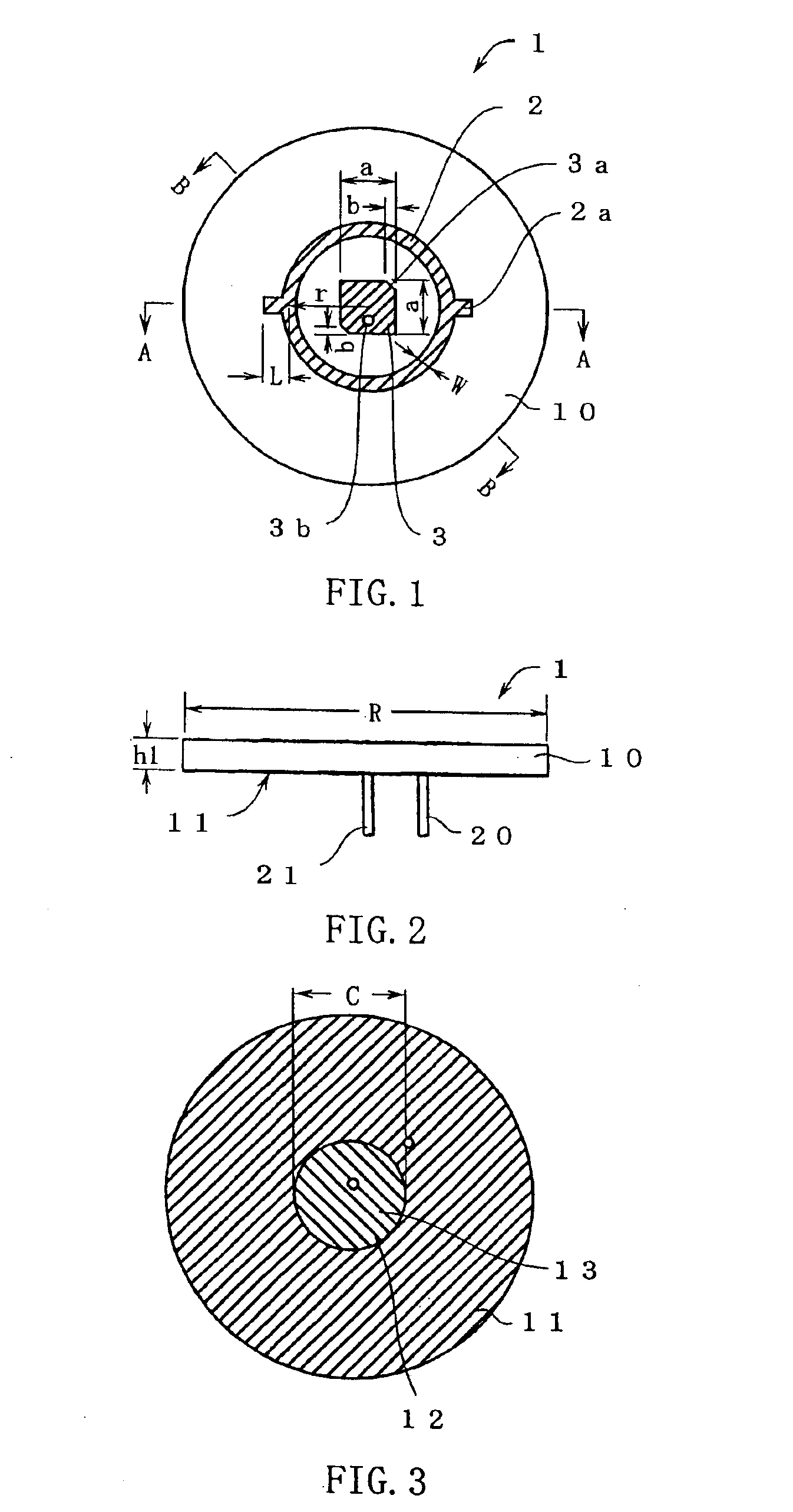
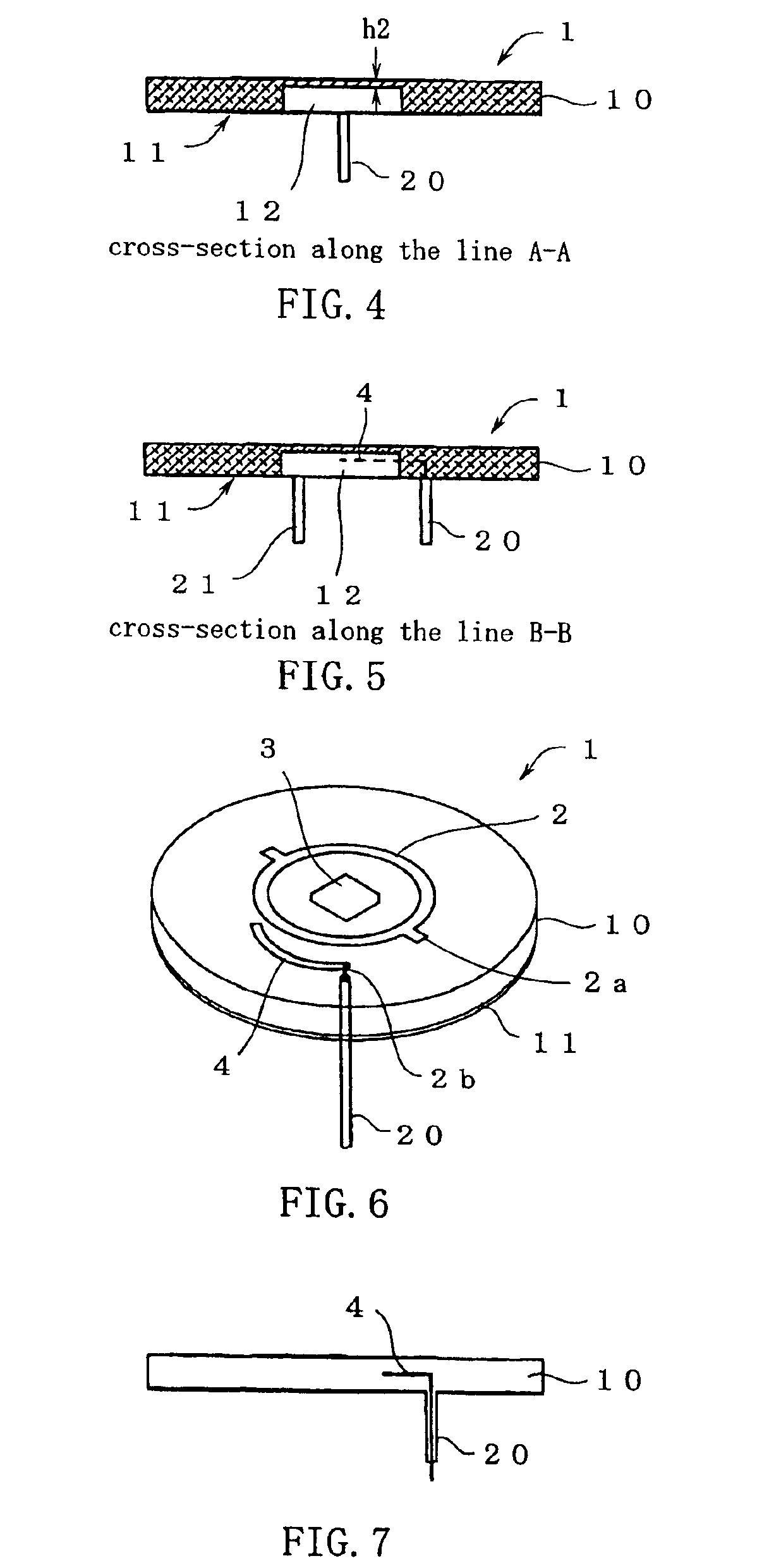
[0075]The constitution of the composite antenna according to the present invention is shown in FIGS. 1 through 7, where FIG. 1 is a planar view of the composite antenna according to the present invention; FIG. 2 is a side view thereof; FIG. 3 is a rear view thereof; FIG. 4 is a cross-sectional view thereof along the line A—A; FIG. 5 is a cross-sectional view thereof along the line B—B; FIG. 6 is a perspective view showing an outline constitution thereof; and FIG. 7 is a side view showing an outline constitution thereof.

[0076]The first composite antenna 1 shown in FIGS. 1 to 7 is a two-frequency composite antenna and is constituted to operate as a 5.8 GHz-band DSRC antenna for ETC or similar and as a 1.5 GHz-band GPS antenna, for example. A first antenna 2 is formed by a print pattern in the upper surface of a circular dielectric substrate 10 which constitutes the composite antenna 1. The first antenna 2 is a loop antenna, and is constituted as a circularly polarized antenna as a res...

second embodiment

[0088]Next, the constitution of the composite antenna according to the present invention is shown in FIGS. 21 to 28, where FIG. 21 is a planar view of a second composite antenna 100 according to the present invention; FIG. 22 is a side view thereof; FIG. 23 is a rear view thereof; FIG. 24 is a cross-sectional view thereof along the line A—A; FIG. 25 is a cross-sectional view thereof along the line B—B; FIG. 26 is a perspective view showing the outline constitution thereof; and FIG. 27 is a side view showing the outline constitution thereof.

[0089]The second composite antenna 100 shown in FIGS. 21 to 27 is a two-frequency composite antenna and is constituted to operate as a 5.8 GHz-band DSRC antenna for ETC or similar and as a 1.5 GHz-band GPS antenna, for example. A first antenna 102 is formed by a print pattern in the upper surface of a circular dielectric substrate 110 which constitutes the composite antenna 100. The first antenna 102 is a loop antenna, and is constituted as a circ...

third embodiment

[0098]Next, the constitution of the composite antenna according to the present invention is shown in FIGS. 29 through 35, where FIG. 29 is a planar view of a third composite antenna 200 according to the present invention; FIG. 30 is a side view thereof; FIG. 31 is a rear view thereof; FIG. 32 is a cross-sectional view thereof along the line A—A; FIG. 33 is a cross-sectional view thereof along the line B—B; FIG. 34 is a perspective view showing an outline constitution thereof; and FIG. 35 is a side view showing an outline constitution thereof.

[0099]The third composite antenna 200 shown in FIGS. 29 to 35 is a two-frequency composite antenna and is constituted to operate as a 5.8 GHz-band DSRC antenna for ETC or similar and as a 1.5 GHz-band GPS antenna, for example. A first antenna 202 is formed by a print pattern in the upper surface of a circular dielectric substrate 210 which constitutes the composite antenna 200. The first antenna 202 is a loop antenna, and is constituted as a cir...


PUM


Abstract

An object of the present invention is a small composite antenna that is capable of operating in a plurality of different frequency bands. A first antenna 2 constituting a GPS circularly polarized loop antenna is formed on a dielectric substrate 10. A second antenna 3 constituting an ETC square patch antenna is formed on substantially the same axis as the first antenna 2. An earth pattern is formed in the underside of the dielectric substrate 10, and a recess in whose bottom face an earth pattern is formed so as to lie opposite the second antenna 3 is provided. An arc-shaped feed pattern 4 is electromagnetically coupled to the first antenna 2 so as to supply electricity thereto, whereby this antenna is made to operate as a right-handed circularly polarized antenna. Electricity is supplied by a coaxial cable to the second antenna 3 to cause same to operate as a right-handed circularly polarized antenna.

Description

[0001]This application is the U.S. National Phase under 35 U.S.C. §371 of International Application PCT / JP02 / 11209, filed Oct. 29, 2002, which claims priority of Japanese Patent Application No. 2001-352074, filed Nov. 16, 2001. The International Application was published under PCT Article 21(2) in a language other than English.TECHNICAL FIELD[0002]The present invention relates to a composite antenna in which an antenna which operates in a first frequency band and an antenna which operates in a second frequency band which is lower than the first frequency band are formed on the same substrate.BACKGROUND ART[0003]The short range communication system known as DSRC (Dedicated Short Range Communication) is known. DSRC is a wireless communication system with a radio wave range from a few meters to several tens of meters, and is used in ETC (Electronic Toll Collection Systems), and ITS (Intelligent Transport Systems). ETC is a system in which communications take place between antennae inst...

Claims


Application Information

Patent Timeline
Patent Type & Authority Patents(United States)
IPC IPC(8): H01Q5/00H01Q9/04H01Q1/38H01Q21/28H01Q21/00H01Q21/30H01Q5/10H01Q5/40H01Q13/08
CPCH01Q1/38H01Q9/0407H01Q5/40H01Q9/0457H01Q21/28H01Q9/0428H01Q13/08
Inventor INOUE, JINICHI
Owner HARADA IND CO LTD
Why Eureka
Try Eureka