Image processing apparatus with automatic image pickup feature

a technology of image processing and automatic selection, applied in the direction of instruments, color signal processing circuits, television systems, etc., can solve the problems of small change in images, burdensome processing, awkward representation of recorded images,

Inactive Publication Date: 2005-08-09
SHARP KK
View PDF20 Cites 9 Cited by
  • Summary
  • Abstract
  • Description
  • Claims
  • Application Information

AI Technical Summary

Benefits of technology

[0036]A further object of the present invention is to provide an image processing apparatus that is capable of ensuring a detection of a change in images with only simple processing and without newly adding complex processing and that allows for control of starting and stopping of recording or transmission.
[0060]Thus, such apparatuses can be utilized not only for specialized uses such as for a monitor system but also by a general user with ease and for a variety of purposes, which leads to development of new applications of an image recording apparatus.

Problems solved by technology

When recording only the images in which a state change is detected, however, the recorded images become awkward representations that capture only the changes.
Moreover, there is a problem of no recording taking place when the movement of an intruder is small and thus the change in the images is small.
As a result, not only does the processing become burdensome but also negotiation delay, initial transmission delay, and the like occur in the connection procedure every time connection is established.
Moreover, in the case where image information from before, in the midst of, and after the detection of a state change, particularly, the images from the time before the change are to be transmitted, as described in Japanese Patent Laying-Open No. 6-153199, there is a need to provide a storage unit for retaining input or coded image information in preparation for an occurrence of a change at all times. Moreover, there is a problem of a significant delay after the detection of the state change due to starting the transmission from previous image information.
Thus, after a change takes place, if another change in images takes place during transmission related to the previous change, the latter change would not be detected, or even if it were detected, additional image information corresponding to the latter change cannot be transmitted, since the device is already in the midst of a transmission.
Furthermore, in the case where a prediction error from after motion compensation prediction upon compression coding processing of images is employed in detection of a change as described in Japanese Patent Laying-Open No. 10-285542, the magnitude of the prediction error does not necessary represent the degree of change contained in the images, since the prediction error becomes small if the motion compensation prediction works effectively even when the images contain a motion.
On the other hand, in the case where a change in images is detected using a motion vector as described in Japanese Patent Laying-Open No. 10-322682, the motion vector being utilized is one that was detected for the purpose of image coding processing so that it does not necessarily express an accurate motion in the images.
In addition, complex changes of images and a motion accompanying variation in color and brightness cannot be detected as motions so that they cannot be determined as state changes of images.
Moreover, when an apparatus automatically controls the starting and stopping of recording and transmission of images as described above, it becomes difficult for a user to determine the operative condition of the apparatus from outside, i. e. whether the apparatus is currently recording, transmitting, or being suspended.
In other words, the user is never observing the viewfinder, the monitor, or the like so that the user cannot determine the operative condition of the apparatus even when the condition is being represented on the viewfinder or the monitor.
Thus, the user is unable to identify the operative condition of the apparatus from a remote location.

Method used


Image

  • Image processing apparatus with automatic image pickup feature
  • Image processing apparatus with automatic image pickup feature
  • Image processing apparatus with automatic image pickup feature

Examples


Embodiment Construction

[0067]An embodiment of the image processing apparatus, for instance, an image recording apparatus, according to the present invention will be described in detail below with reference to FIGS. 1 to 5.

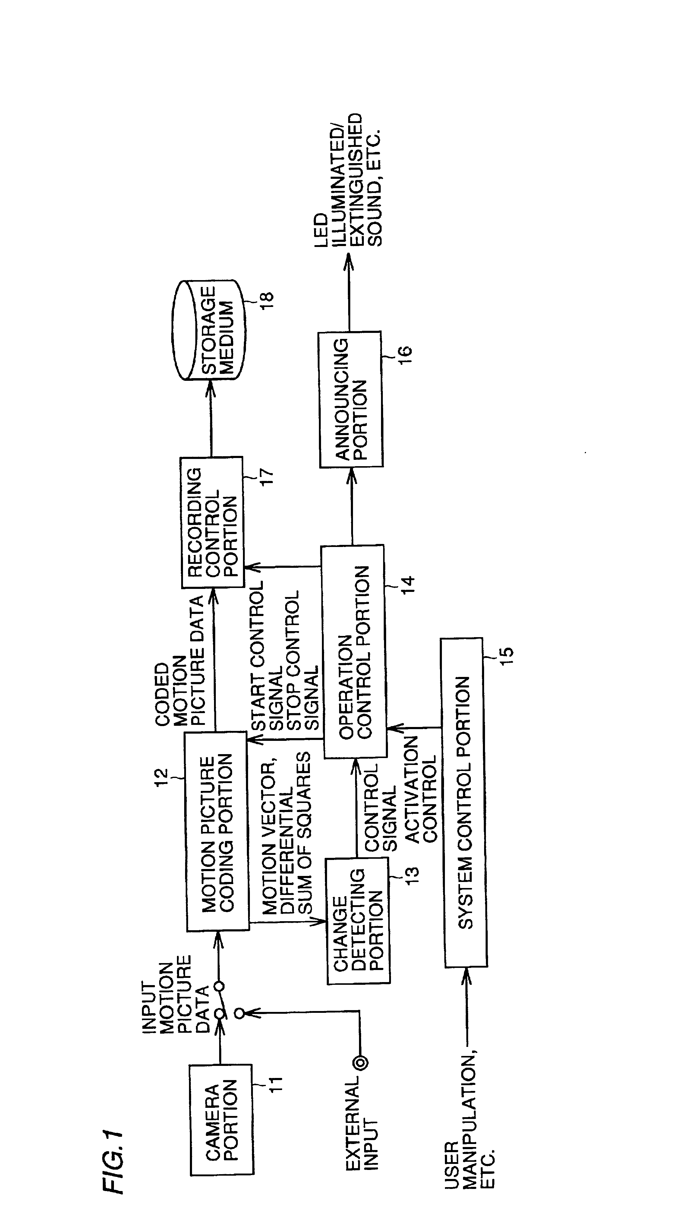
[0068]FIG. 1 is a block diagram illustrating a schematic arrangement in an image recording apparatus of the present embodiment. In FIG. 1, input motion picture data is input from a camera portion 11 for picking up an image or from an external input. The input motion picture data is subjected to compression coding in a motion picture coding portion 12 and coded motion picture data is output.

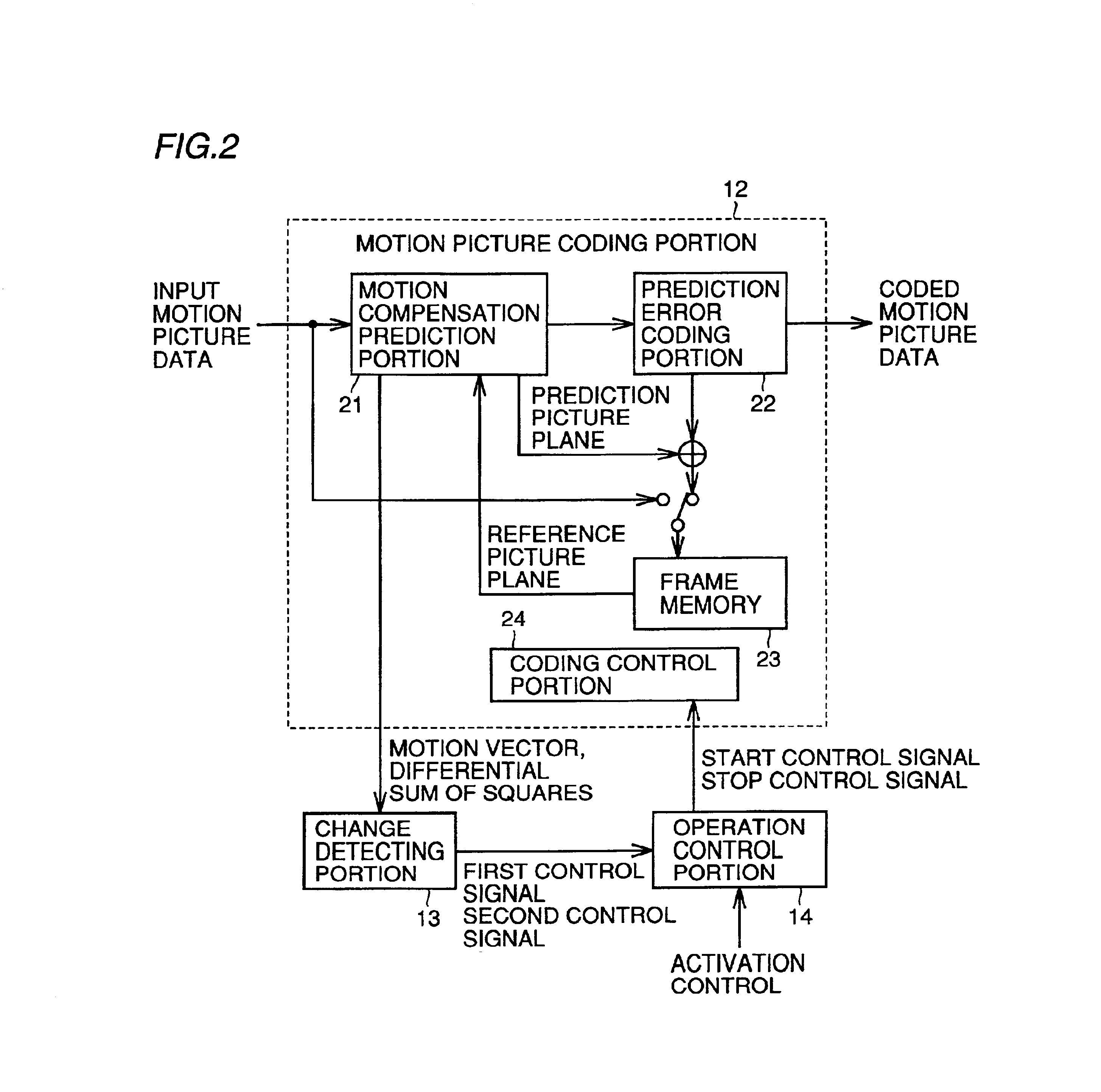
[0069]In motion picture coding portion 12, processing according to motion picture coding scheme such as ITU-T Recommendations H.261, H.262, H.263, H.26L, ISO Standards 11172-2 (MPEG-1), 13818-2 (MPEG-2), 14496-2 (MPEG-4), or nonstandard original scheme is performed, and coded motion picture data of a format that is consistent with the convention according to one of these schemes is output. The coded mo...


PUM


Abstract

The image processing apparatus includes a change detecting portion for outputting a first control signal indicating transition from a small change state to a large change state and a second control signal indicating transition from a large change state to a small change state between picture planes of input motion picture data, and an operation control portion for controlling starting and stopping of recording or transmission of input motion picture data according to the first control signal and the second control signal. During recording or transmission, the operation control portion controls to stop recording or transmission if the first control signal is not output until after a predetermined arbitrary time T1 elapses after the second control signal is output.

Description

BACKGROUND OF THE INVENTION[0001]1. Field of the Invention[0002]The present invention relates to an image processing apparatus for picking up (selecting) a motion picture and recording or transmitting the picked up motion picture, and more specifically, to an image processing apparatus having an automatic image pickup (selecting) feature that is suitable, for instance, for a monitor system and for observations of animal and plant ecology and the like.[0003]2. Description of the Background Art[0004]In recent years, progress in digitization of image equipment is being made due to progress and advances made in the digital signal processing techniques and digital coding techniques for images. In the field of image recording apparatuses, digital video cameras, digital still cameras, and the like are becoming widespread, and in such equipment, an input image signal is first digitized, and image signals are all handled as digital information throughout the processing, from signal processin...

Claims


Application Information

Patent Timeline
Patent Type & Authority Patents(United States)
IPC IPC(8): G08B13/194H04N7/36H04N5/14H04N5/915G06T7/20H04N5/92H04N7/18H04N19/102H04N19/137H04N19/147H04N19/172H04N19/196H04N19/423H04N19/50H04N19/503H04N19/51
CPCG08B13/19669G08B13/19676H04N5/147G08B13/19602G08B13/19604H04N19/51
Inventor HIBI, KEIICHISHIOI, MASAHIRO
Owner SHARP KK
Why Eureka
Try Eureka