Speaker diaphragm

a diaphragm and speaker technology, applied in the direction of transducer diaphragms, electromechanical transducers, instruments, etc., can solve the problems of high current supply to the voice coil, severe installation and operation conditions of the subwoofer, etc., and achieve the effect of high heat radiation efficiency

Inactive Publication Date: 2005-08-16
PIONEER CORP +1
View PDF6 Cites 14 Cited by
  • Summary
  • Abstract
  • Description
  • Claims
  • Application Information

AI Technical Summary

Benefits of technology

[0009]In order to solve the above described problems, the present invention aims to provide a speaker diaphragm that possesses a high heat radiation efficiency.

Problems solved by technology

In other words, the subwoofer is subjected to severe installation and operation conditions.
Specifically, a great amount of current is supplied to the voice coil.

Method used


Image

  • Speaker diaphragm
  • Speaker diaphragm
  • Speaker diaphragm

Examples


Embodiment Construction

[0018]An embodiment of the present invention will be described in reference to the accompanying drawings.

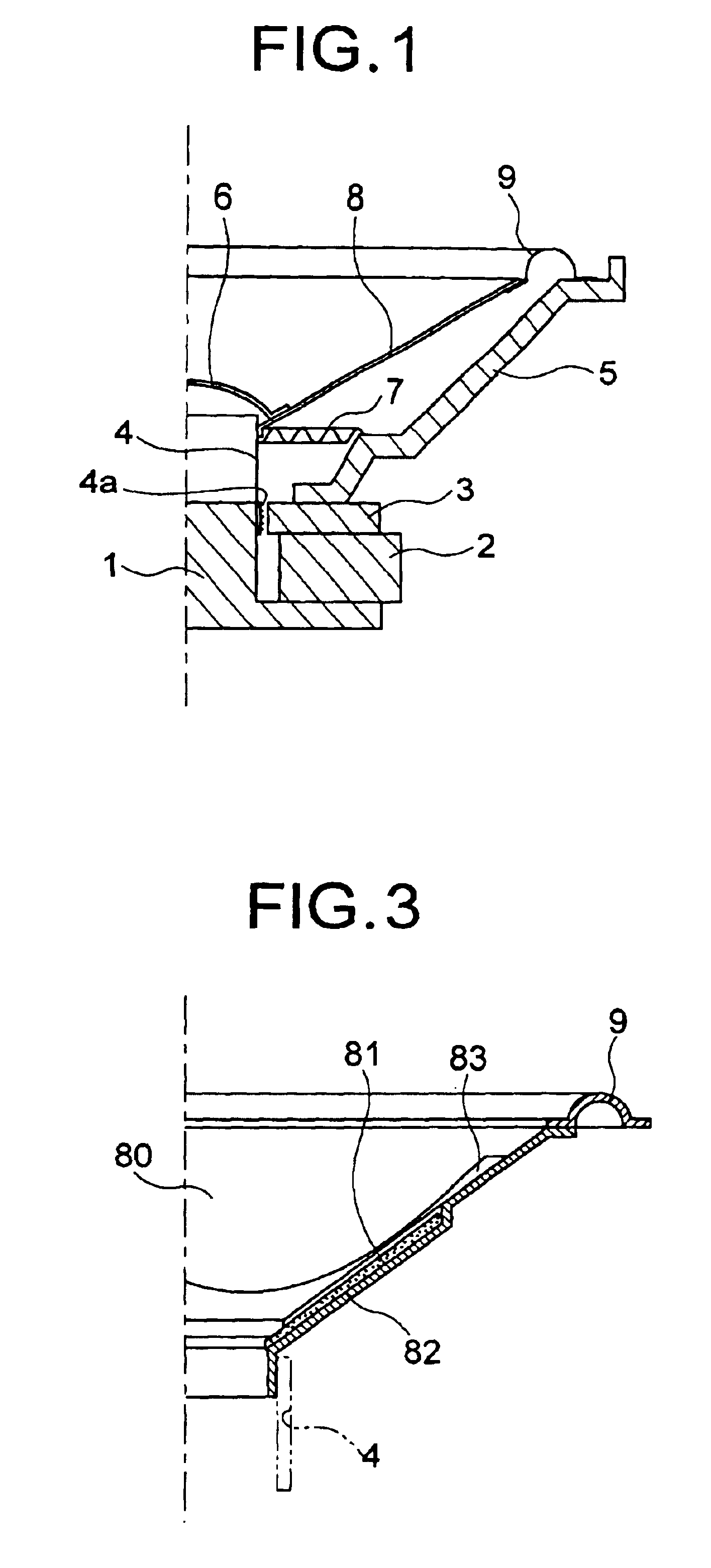
[0019]Referring first to FIG. 2, illustrated is an example of a speaker diaphragm, which is made by resin injection molding, according to the present invention.

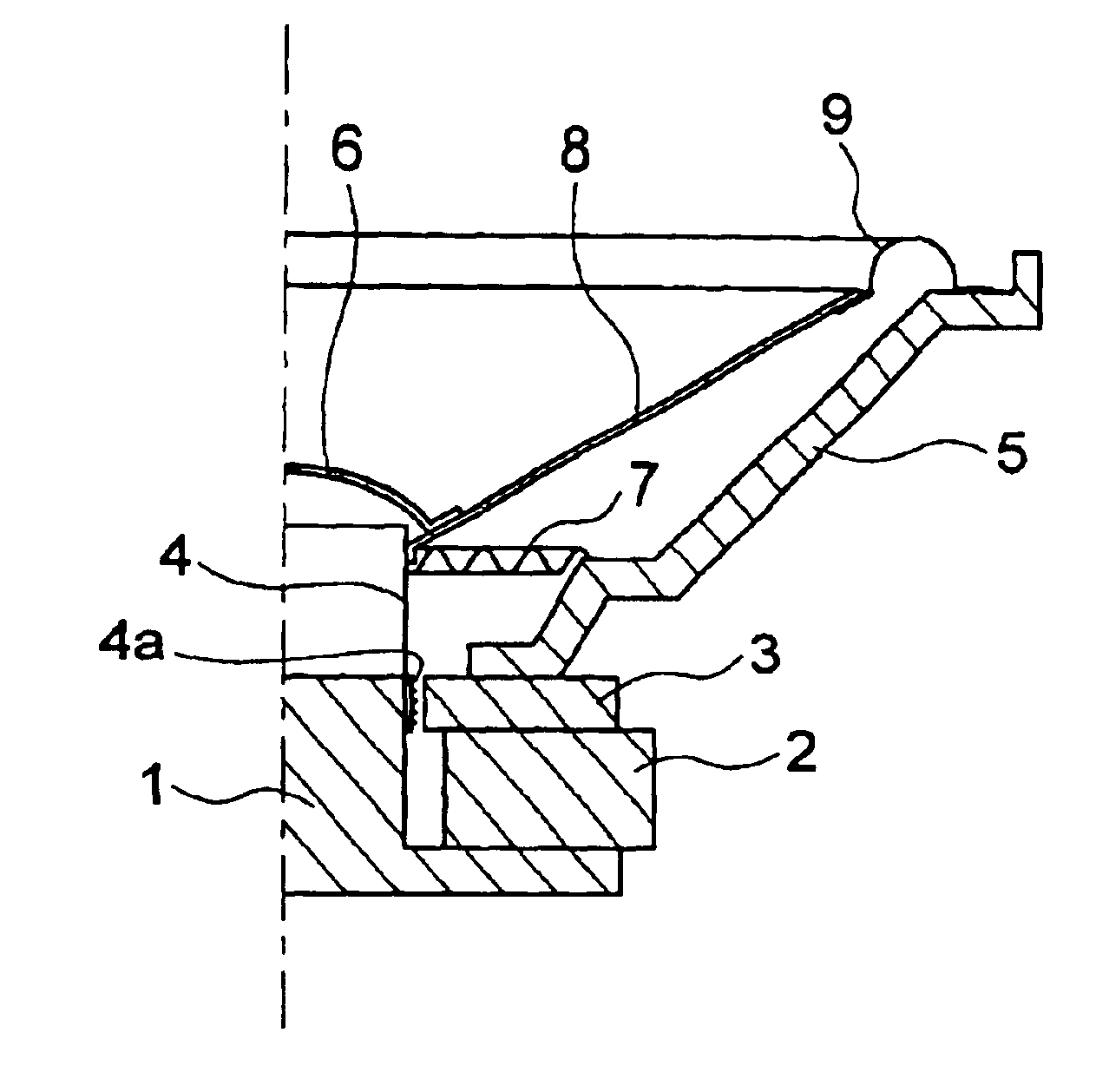
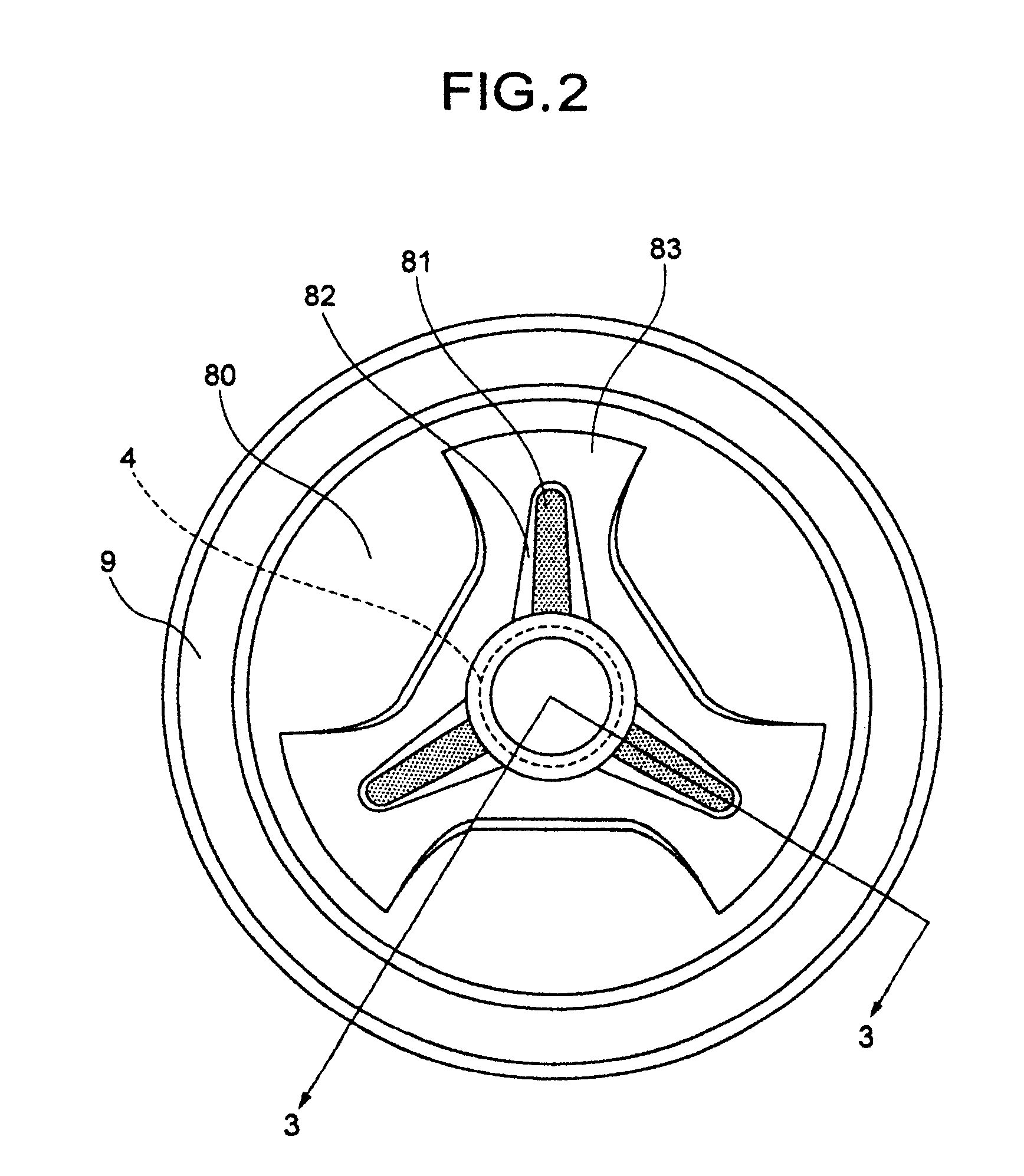
[0020]This speaker diaphragm includes a diaphragm main body 80 and an edge 9 around the outer periphery of the main body 80. The diaphragm main body 80 is molded by an injection molding process using a resin such as PP (polypropylene). The speaker diaphragm also includes a metallic plate 81 of about 1 mm thickness. The metallic plate 81 may be made from aluminum or an aluminum alloy, and attached to the main acoustic side of the diaphragm main body 80 adjacent a voice coil bobbin 4. The voice coil bobbin 4 is attached to the diaphragm main body 80. The metallic plate 81 serves as heat radiation fins so that heat transferred to a neck portion of the diaphragm main body 80, which firmly supports the voice coil bobbin 4, is r...


PUM


Abstract

A speaker diaphragm that has a high heat-radiation efficiency. The speaker diaphragm includes a diaphragm main body made from a resin, and a metallic plate adhered to a major acoustic surface of the diaphragm main body adjacent a voice coil bobbin. The voice coil bobbin is attached to the diaphragm man body.

Description

BACKGROUND OF THE INVENTION[0001]1. Field of the Invention[0002]The present invention relates to an electroacoustic transducer such as an electrodynamic loudspeaker, and more particularly to a diaphragm of a speaker.[0003]2. Description of the Related Art[0004]Referring to FIG. 1 of the accompanying drawings, illustrated is a partial cross sectional view of a conventional electrodynamic loudspeaker, which is one example of an electroacoustic transducer. The electrodynamic loudspeaker includes a pole yoke 1 projecting from a center portion of a back plate, and a magnet 2 placed around the pole yoke 1. A top plate 3 is placed on the magnet 2 such that a magnetic gap is created between the top plate 3 and pole yoke 1 to form a magnetic circuit. The top plate 3 is fixedly secured to a frame 5. A voice coil bobbin 4, having a voice coil 4a wound therearound, is positioned to oscillate in the magnetic gap and is supported by a damper 7. A cone-shaped diaphragm 8 is connected to the voice ...

Claims


Application Information

Patent Timeline
Patent Type & Authority Patents(United States)
IPC IPC(8): H04R9/02H04R7/12H04R9/00H04R7/00H04R9/04H04R7/02H04R7/04
CPCH04R7/122H04R9/022H04R2307/027H04R2307/029
Inventor ABE, YASUHISASUZUKI, TAKASHIMATSUMOTO, KOJITAKAYAMA, KOJI
Owner PIONEER CORP
Why Eureka
Try Eureka