System and method for dispensing soap

a soap and system technology, applied in the field of system and method for soap dispensing, can solve the problems of low manufacturing cost, low cost of manufacture, and device structure elements that do not provide consistent operation, so as to achieve the effect of reducing friction, reducing costs, and facilitating movemen

Inactive Publication Date: 2005-08-16
RUBBERMAID COMMERCIAL PRODUCTS
View PDF74 Cites 136 Cited by
  • Summary
  • Abstract
  • Description
  • Claims
  • Application Information

AI Technical Summary

Benefits of technology

[0008]The soap delivery tube and pump assembly are centrally mounted on the top of a fluid soap reservoir container. As a result, a new delivery tube, pump assembly, and fluid soap container may be provided with a full soap reservoir assembly upon each replacement of an empty soap reservoir assembly. Moreover, as a result of the centrally disposed location of the elongated delivery tube and pump assembly on the reservoir container, the delivery tube may be readily extended axially through a curved, rigid dispensing spout mounted to the countertop, and the delivery tube may be readily rotated about its longitudinal axis for ease of movement in the dispensing spout when the unitary reservoir container, pump assembly and delivery tube assembly are rotated during installation of a new, full reservoir container and pump assembly.
[0010]The fluid soap reservoir container and pump assembly of the invention also provides advantages over fluid soap dispensing systems of the prior art. A standard manufactured pump assembly may be used in the fabrication of the reservoir module of the invention due to the central position of the pump and of the dispensing tube relative to the soap container. This permits the reservoir module to be filled using standard bottle filling equipment found in the facilities of most contract bottle fillers. This application of standard equipment provides a substantial cost savings in the production of soap refill reservoir modules in accordance with the invention.
[0011]The central location of the pump assembly and delivery spout on the reservoir module also permits rapid installation of the reservoir module on the motor housing of the dispenser by a simple rotation of the soap reservoir and pump assembly to complete a bayonet type connection with the fixed pump housing of the invention. Moreover, the construction of the reservoir and pump assembly enables the mass production of a reliable refill unit.
[0012]The combination of the rigid dispensing spout anal fluid soap delivery tube moveable inside the spout permits economy of construction not found in prior automatic soap dispensers. The spring in the pump assembly mounted on the soap container provides the force to return the delivery tube to its start position after a dose of fluid soap has been dispensed. The spout configuration and construction is adapted to provide ease of movement of the delivery tube in the spout, with a minimum of friction produced. The elongated delivery tube of the invention is rigid enough to withstand hydraulic pressure developed during the dispensing operation, and flexible enough to move substantially frictionless relative to the interior of the dispensing spout.
[0013]The motor housing of the invention mounts to a shank extending through a countertop, such that the housing may be readily rotated away from the underside of the sink bowl, and away from plumbing fixtures. This is a result of the central mounting of the operative components extending from the reservoir module, through the motor housing, to the entrance to the dispensing spout.

Problems solved by technology

However, these devices do not incorporate structural elements that desirably provide consistent operation, ease of installation and replaceability, and low cost of manufacture.

Method used


Image

  • System and method for dispensing soap
  • System and method for dispensing soap
  • System and method for dispensing soap

Examples


Embodiment Construction

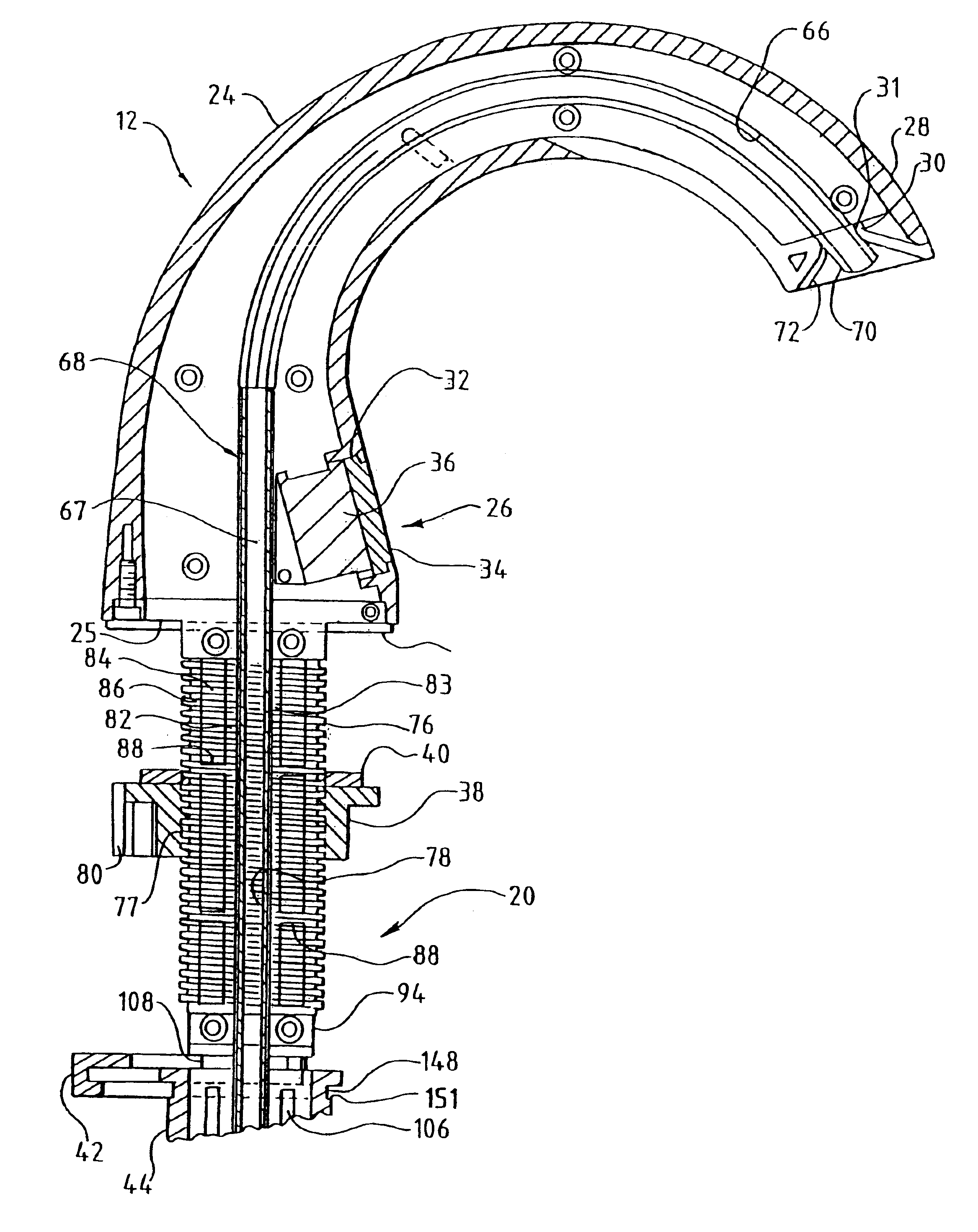
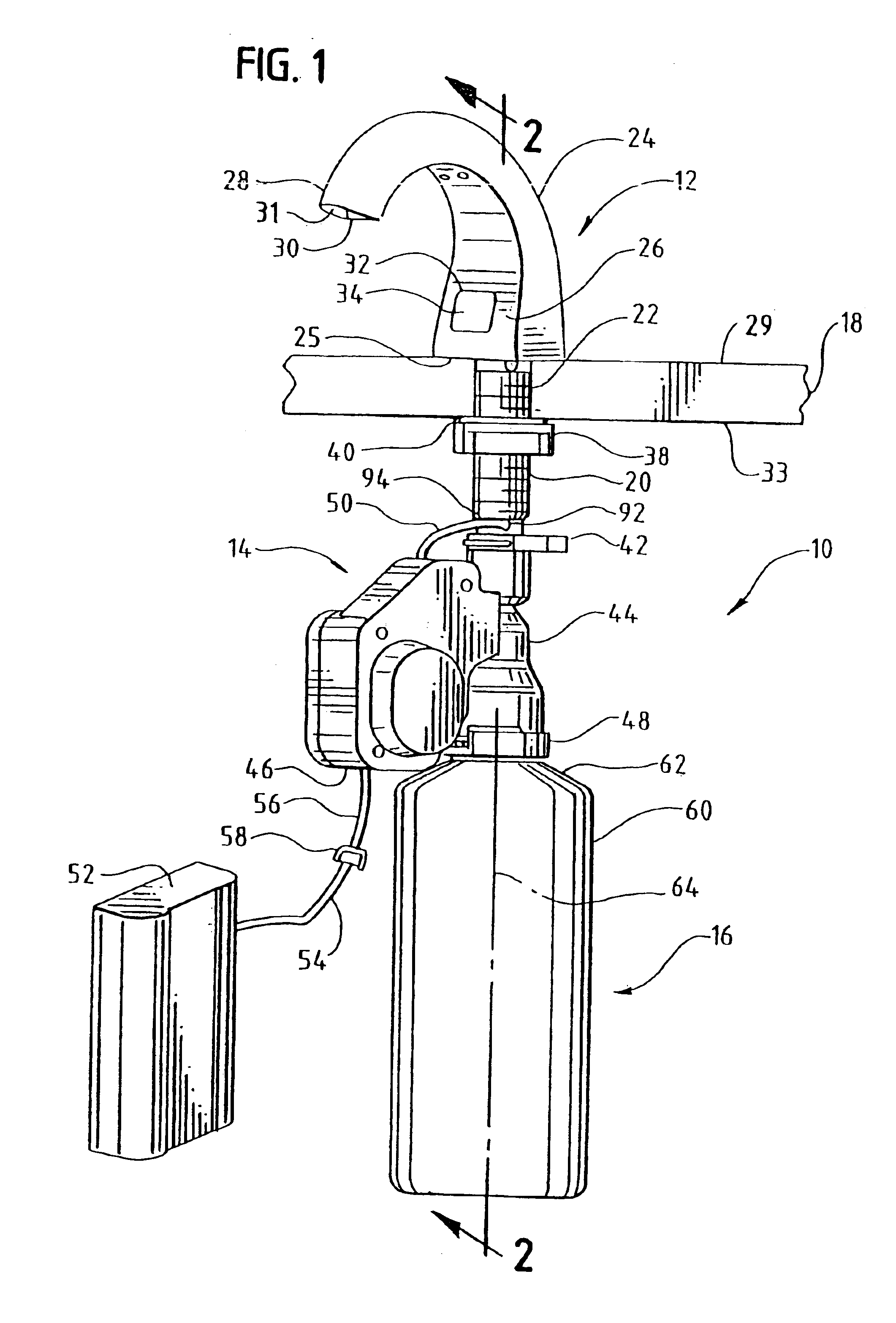
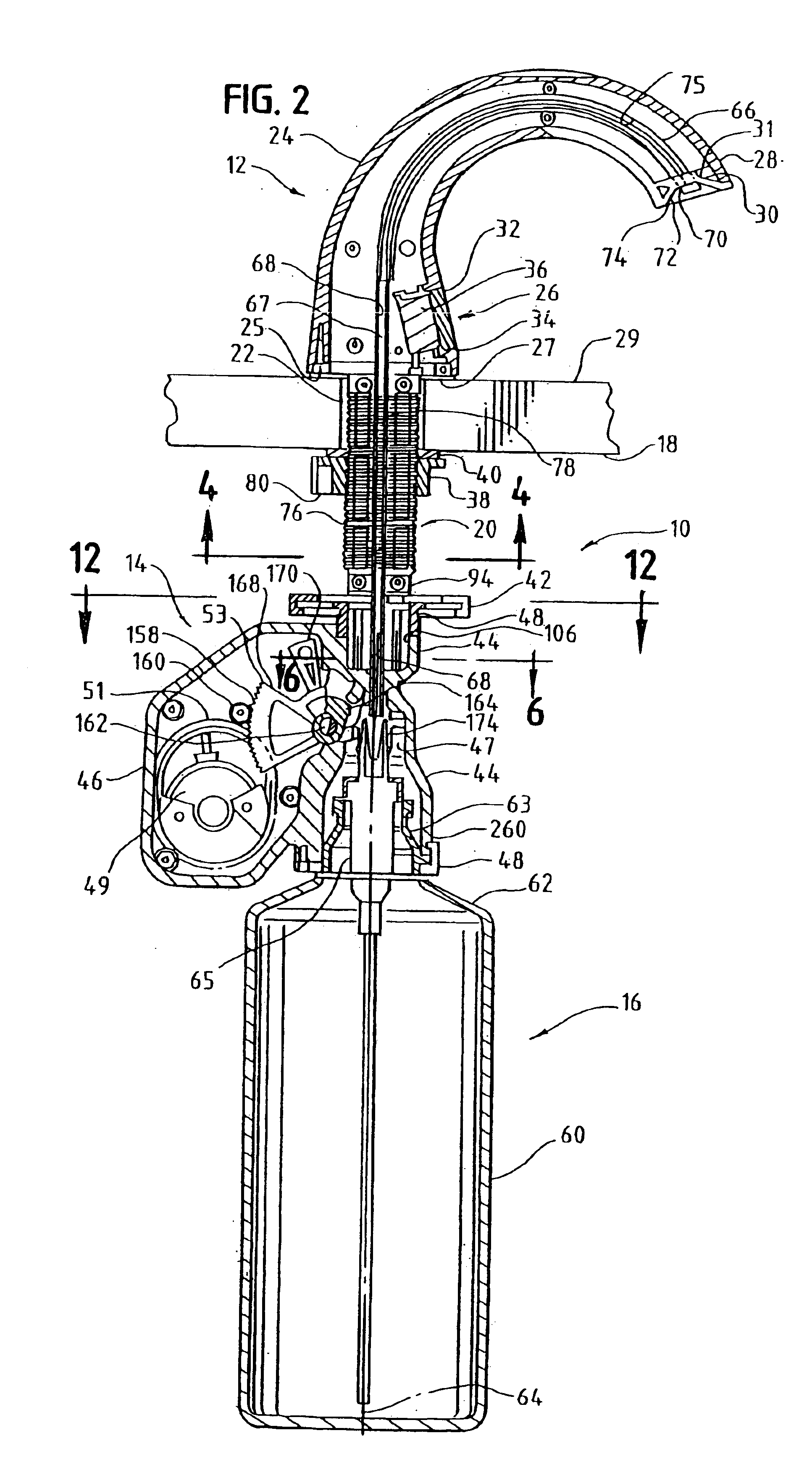
[0049]Referring to FIG. 1, an automatic fluid soap dispensing system constructed in accordance with the invention is generally designated by the numeral 10. The fluid dispensing system 10 may include three major assemblies: a spout and mounting shaft assembly 12, a motor housing and support assembly 14, and a reservoir module and pump assembly 16. The fluid dispensing system 10 is shown mounted on a countertop 18 with a support shaft 20 extending through an aperture 22 extending, where the aperture 22 is disposed through the countertop 18. Countertop 18 may be a sink countertop and support shaft 20 may be hollow (hollow portion 84) and threaded (external threads 76).

[0050]Support shaft 20 is fixed to, or may form a part of, rigid spout 24. Rigid spout 24 may include a base 25 abutting countertop 18, an upwardly extending electronic eye housing portion 26, and a curved dispensing portion 28. In the illustrated embodiment of FIG. 2, a resilient pad 27 is disposed between base 25 of th...


PUM

PropertyMeasurementUnit
voltageaaaaaaaaaa
angleaaaaaaaaaa
angleaaaaaaaaaa

Abstract

A method of dispensing soap from a fluid dispensing system is disclosed. The method includes the steps of presenting a tube having a tube end disposed at a first position within an indented portion of a spout of the fluid dispensing system, sensing an object below the tube end, in response to sensing the object, expelling said soap from the tube end by drawing the tube end further within the indented portion to a second position, and returning the tube end to the first position.

Description

[0001]The present patent application is a divisional application of U.S. patent application Ser. No. 10 / 163,137, filed on Jun. 4, 2002, now U.S. Pat. No. 6,651,851, which is a divisional application of U.S. patent application Ser. No. 09 / 525,976, filed Mar. 15, 2000, now U.S. Pat. No. 6,467,651, which claims the benefit of prior filed U.S. Povisional Applications having the provisional application No. 60 / 154,101, filed Sep. 15, 1999, and the provisional application No. 60 / 156,987, filed Oct. 1, 1999. No new matter has been added.[0002]The invention relates generally to automatically operated devices to repeatedly dispense fluid material from a replaceable reservoir, and more particularly to a fluid dispensing apparatus and method that dispenses fluid material automatically in response to sensing the presence of a user.BACKGROUND OF THE INVENTION[0003]Users of modern public washroom facilities increasingly desire that each of the fixtures in the washroom operate automatically without...

Claims


Application Information

Patent Timeline
Patent Type & Authority Patents(United States)
IPC IPC(8): A47K5/00A47K5/12A61L9/12A61L9/14B05B12/02B05B11/00B05B12/00E03D9/00A47L15/00B65D88/54B67D7/56G01F11/06G01F11/30G01F11/36G01F11/38G01F11/42
CPCA47K5/1217A61L9/12A61L9/145B05B11/3008B05B11/3052B05B12/02E03D9/007G01F11/38A47K2005/1218B05B11/3001B05B11/1008B05B11/1052B05B11/1001
Inventor MUDERLAK, KENNETH J.HSIEH, ROCKY
Owner RUBBERMAID COMMERCIAL PRODUCTS
Why Eureka
Try Eureka