Rotor system for helicopters

a helicopter and rotor technology, applied in the field of rotor systems for helicopters, can solve the problems of complicated and expensive helicopters, particularly difficult control of model helicopters, and difficulty in controlling helicopters, etc., and achieve the effects of more complicated and expensive, difficult control, and expensive repair

Inactive Publication Date: 2005-08-16
ARLTON PAUL E
View PDF6 Cites 69 Cited by
  • Summary
  • Abstract
  • Description
  • Claims
  • Application Information

AI Technical Summary

Benefits of technology

[0004]With all of their rotating rotor blades, gears, and mechanical linkages helicopters are typically more complicated and expensive than other types of aircraft such as fixed-wing airplanes. Helicopters are also generally more difficult to fly than airplanes, and model helicopters are particularly difficult to control. As a result, pilot of model helicopters frequently crash and damage their models. Model helicopters can be very expensive to repair, so relatively few modelers have the patience, skill, and budget to master them. Components that reduce the complexity and cost of helicopters make helicopters more available to the general public, easier to maintain and repair, and generally more competitive with other types of aircraft.
[0005]Tail rotor systems on he

Problems solved by technology

With all of their rotating rotor blades, gears, and mechanical linkages helicopters are typically more complicated and expensive than other types of aircraft such as fixed-wing airplanes.
Helicopters are also generally more difficult to fly than airplanes, and model helicopters are particularly difficult to control.
As a result, pilot of model helicopters frequently crash and damage their models.
Model helicopters can be very expensive to repair, so relatively few modelers have the patience, skill, and budget to master them.
Tail rotors are also more likely t

Method used


Image

  • Rotor system for helicopters
  • Rotor system for helicopters
  • Rotor system for helicopters

Examples


Embodiment Construction

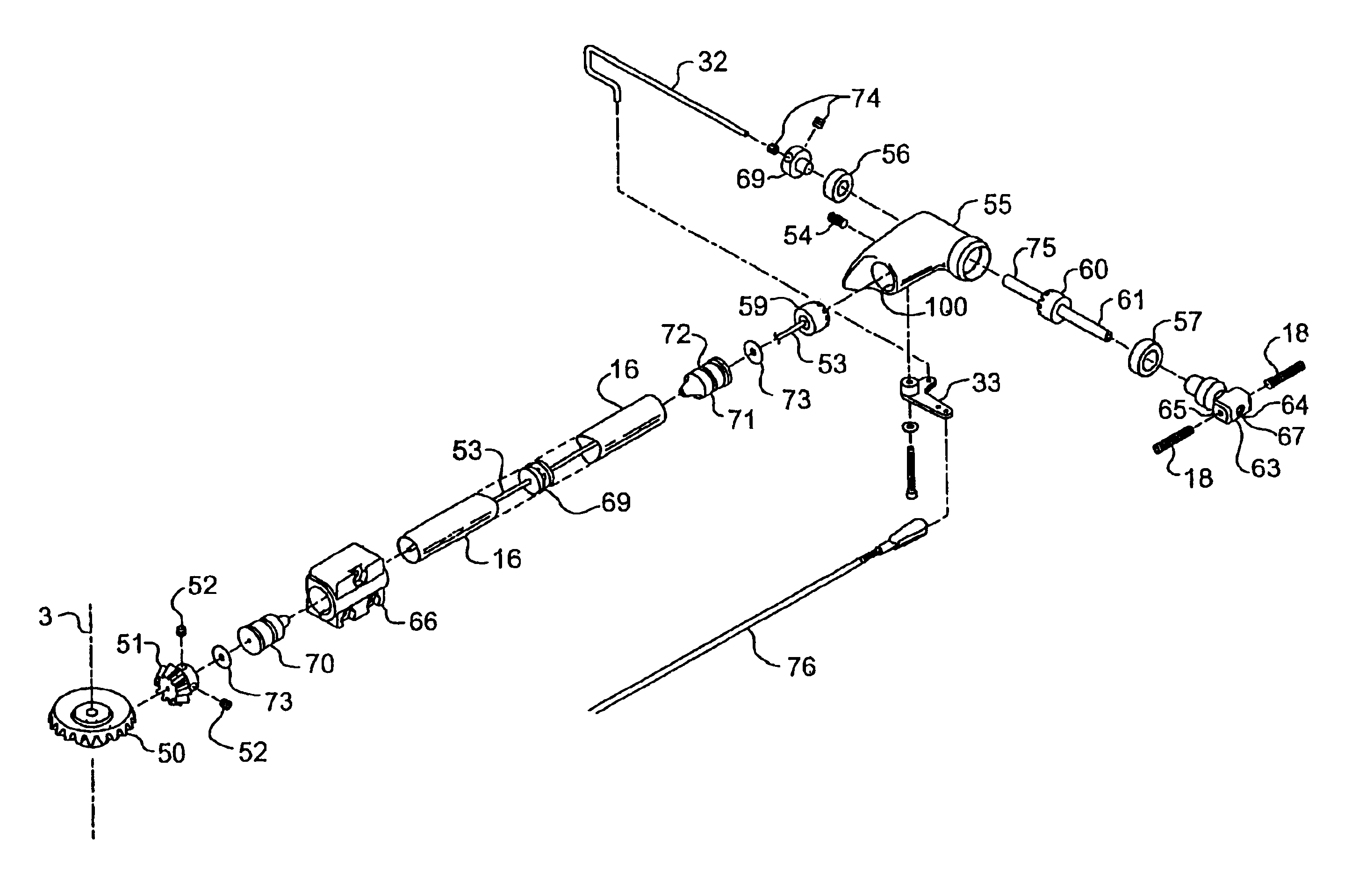
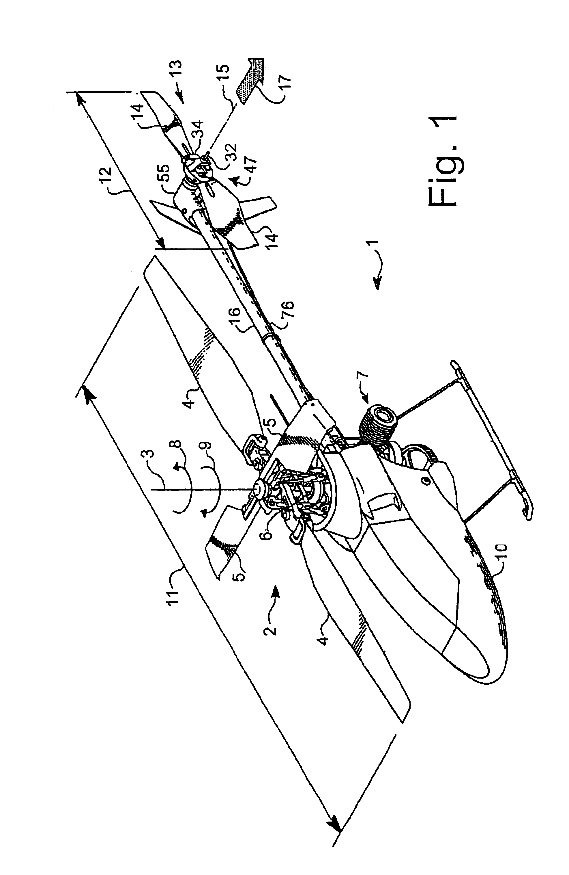
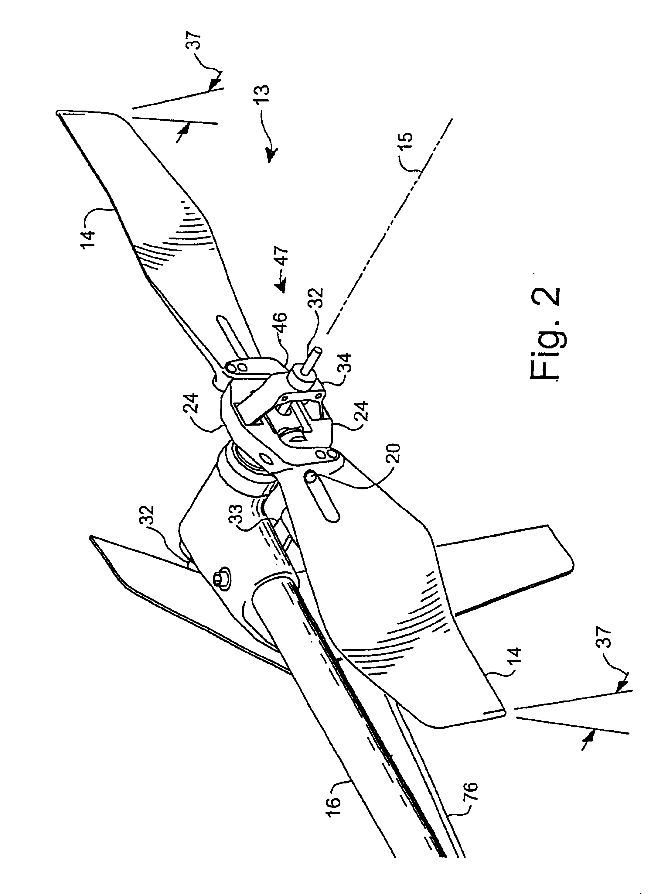
[0029]Referring to FIG. 1, a helicopter 1 is designed to include a large main rotor 2 which rotates about a main rotor axis of rotation 3 to lift helicopter 1 into the air. Helicopter 1 also includes a smaller tail rotor 13 which rotates about a tail rotor axis of rotation 15 to counteract the torque produced by main rotor 2 and steer helicopter 1. Tail rotor 13 is mounted at the end of a tail boom 16.

[0030]Both main rotor 2 and tail rotor 13 of helicopter 1 are driven by a power plant 7 such as engine or an electric motor (not shown) usually located within the fuselage (body) of helicopter 1 near main rotor shaft 6 (mostly hidden) although tail rotor 13 could also be operated by, for instance, a separate motor or engine (not shown) mounted at the end of tail boom 16. A streamlined fuselage shell 10 covers the front of helicopter 1, but does not extend back to tail rotor 13. In alternative embodiments, the fuselage shell may extend back to tail rotor 13 and enclose the tail boom 16....


PUM


Abstract

A tail rotor system for a helicopter includes a gear box housing retainer (66) coupled to the tail boom (16) of the helicopter. The tail rotor system also includes a power-limiting device (50) configured to disconnect the tail rotor from a power plant for driving the tail rotor about a rotor axis of rotation.

Description

[0001]This application claims the benefit of Provisional Application No. 60 / 317,003, filed Sep. 4, 2001.BACKGROUND AND SUMMARY[0002]The present disclosure relates to rotor systems for helicopters and similar aircraft, and in particular to tail rotors.[0003]Helicopters are flying machines which can fly in any direction or hove over a point on the ground without moving. Helicopters usually have a single main rotor mounted on top of a body or fuselage of the helicopter to generate a lift force to hold the helicopter in the air, and a tail rotor or other yaw control system to maintain directional control of the helicopter. Several different yaw control systems have been developed (such as blown tail booms and shrouded fans), but traditional tail rotor systems with exposed tail rotor blades are still the most popular.[0004]With all of their rotating rotor blades, gears, and mechanical linkages helicopters are typically more complicated and expensive than other types of aircraft such as f...

Claims


Application Information

Patent Timeline
IPC IPC(8): B64C27/00B64C27/14B64C27/82B64C39/00B64C39/02B64C27/12
CPCA63H27/12B64C27/12B64C27/14
Inventor ARLTON, PAUL E.
Owner ARLTON PAUL E
Why Eureka
Try Eureka