
Vibration-dampened tool for working in metallic material

a vibration-dampened, metal-based technology, applied in the direction of manufacturing tools, wrench drills, wood boring tools, etc., can solve the problems of high sound level, hard metal borders that result, and have not given any suitable noise silencing

Inactive Publication Date: 2005-08-16
SANDVIK INTELLECTUAL PROPERTY AB
View PDF25 Cites 28 Cited by
  • Summary
  • Abstract
  • Description
  • Claims
  • Application Information

AI Technical Summary

Benefits of technology

[0008]Hereby there is achieved an apparatus for a tool with substantially improved sound and vibration damping which is useful at drilling as well as at milling or e.g. interior lathing. As a result of this, the new tool permits a substantial reduction of the sound level caused by the proper metal working of the workpiece. At the same time, such a tool becomes less sensitive to vibrations, which arise by virtue of variations of the cutting forces.

Problems solved by technology

At working of holes in metallic materials, problems arise with the high sound level caused by vibrations from the working and the machine sound.
However, the hard metal borders that result have not turned out to give any suitable silencing of noise.

Method used


Image

  • Vibration-dampened tool for working in metallic material
  • Vibration-dampened tool for working in metallic material
  • Vibration-dampened tool for working in metallic material

Examples


Embodiment Construction

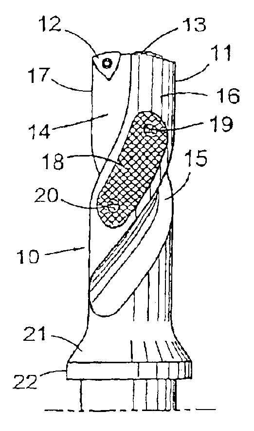
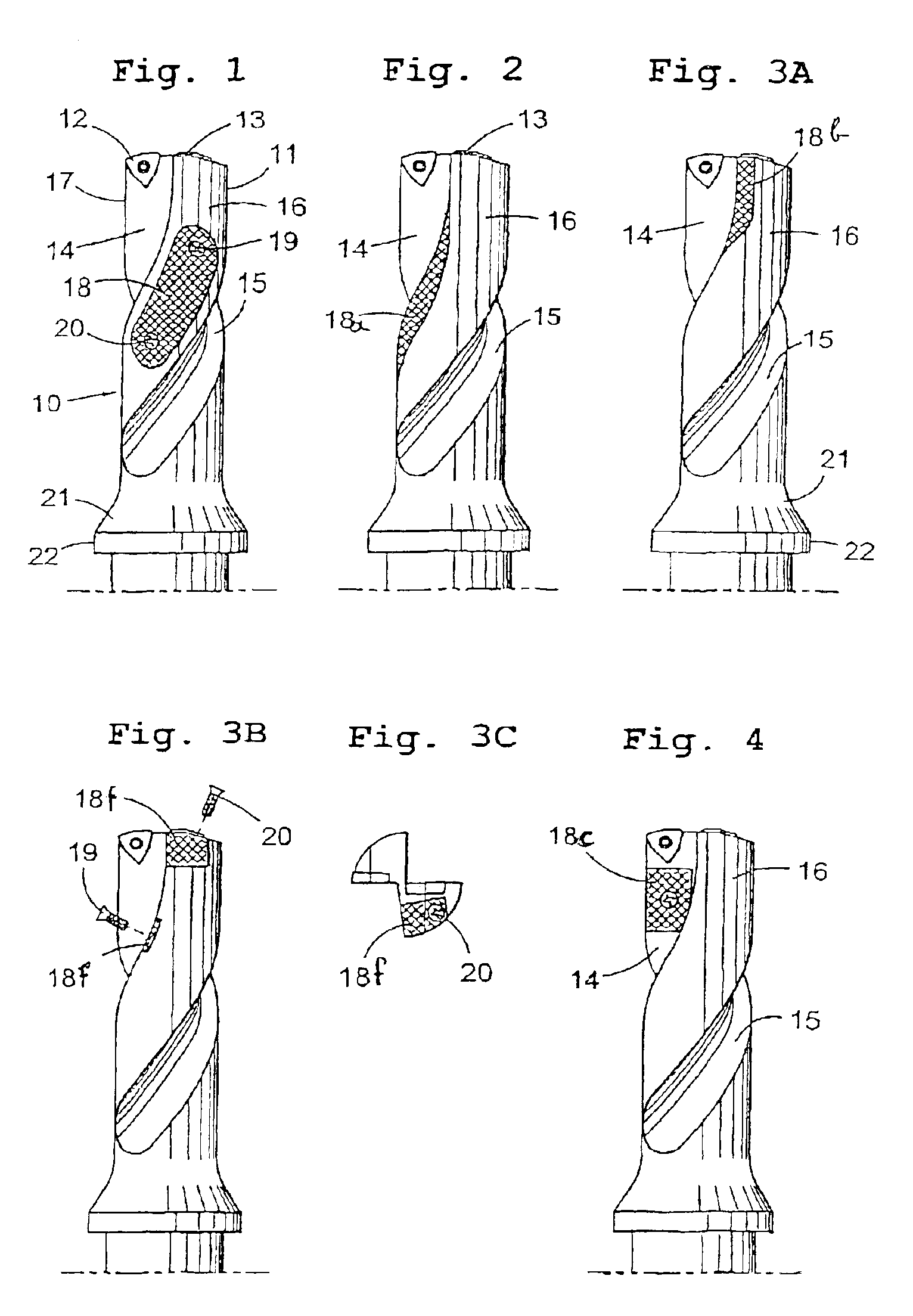
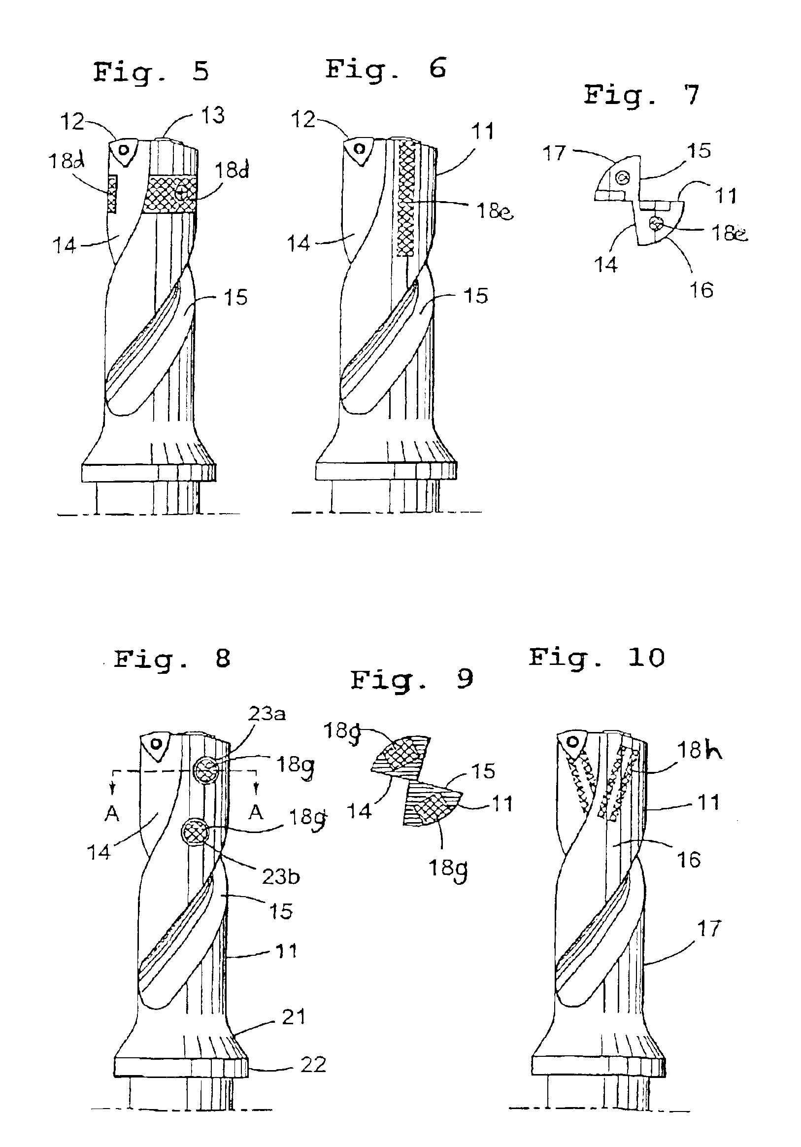
[0033]The present invention stems from the realization that if a moving body (holder body) carries another body (carried body) which is permitted to move relative to the holder body during movement (e.g., rotation) of the carrier body, the relative movement will serve to dissipate energy and thus dampen vibrations and noise of the carrier body. By “relative movement” is meant not only relative sliding movement (which dissipates energy by the generation of friction that is converted into heat), but also deformation of the carried body (with or without sliding movement). Thus, if the carried body is formed of a medium (or a composite or a mix of materials, e.g., fluids, sand, plastics, rubbers, metals and cemented carbides) having less density and / or lower Young's modulus than the holder body (e.g., steel, tungsten) the carried body will tend to deform during acceleration / deceleration, and every part of the carried body that is deformed will dissipate energy (i.e., dampen vibration) t...


PUM

PropertyMeasurementUnit
Metallic bondaaaaaaaaaa

Abstract

A drill for working in metallic materials includes a tool body having located in its front end at least one cutting insert, wherein the tool body is provided with one or several damping elements mounted such that during machining, a relative movement (i.e., sliding and / or deformation) of the tool body and the damping element is allowed to occur.

Description

[0001]This is a continuation-in-part of International Application No. PCT / SE01 / 02691 filed Dec. 6, 2001, the entire content of which is hereby incorporated by reference.BACKGROUND OF THE INVENTION[0002]The present invention relates to a drilling tool for working in metallic material, more precisely a tool of the type that comprises a tool body having at least one cutting insert exposed for working a workpiece. The tool may e.g. be formed as a drill having flutes extending in its longitudinal direction, which flutes join to the outer and inner inserts, respectively, in order to serve as grooves for chip release.[0003]The present invention also relates to a damping device adapted to be arranged on a tool body.[0004]At working of holes in metallic materials, problems arise with the high sound level caused by vibrations from the working and the machine sound. Hitherto known drills have not been provided with built-in / added damping devices formed in such a way that a suitable sound and v...

Claims


Application Information

Patent Timeline
IPC IPC(8): B23B29/02B23B29/00B23C5/00B23B51/04F16F15/10B23B51/00B23B51/08
CPCB23B29/022B23B51/048B23C5/003F16F15/10B23B2250/16Y10T82/2585Y10T408/76Y10T409/304312Y10T408/89Y10T408/907B23B51/00
Inventor BERGHOLT, MARIE-LOUIEKARLSSON, LEIFTUBINGER, KLAS
Owner SANDVIK INTELLECTUAL PROPERTY AB
Learn More