Endoscope apparatus

Inactive Publication Date: 2005-08-16
KK TOSHIBA
View PDF11 Cites 230 Cited by
  • Summary
  • Abstract
  • Description
  • Claims
  • Application Information

AI Technical Summary

Benefits of technology

[0014]According to the present invention, in addition to providing visual feedback of the amount of feed fluid and sucked fluid to an operator, enabling fine flow control, it is possible for nearby medical

Problems solved by technology

In an endoscope apparatus using the mechanical valve system, however, because of the complexity of the tubing, it is necessary when cleaning the apparatus to remove valves and wash and sterilize them separately, and additionally to grease sliding parts after cleaning.
Additionally, because of intricate splitting of the tubing, brushing during cleaning requires a large amount of time.
Maintenance, such as making connections the cleaning apparatus, is also complex and difficult.
In addition, there is the problem of crushing a polyp when polyps are picked using suction.
Because of the on/off control used in the solenoid valve system of the past, this system was not suitable for use by an operator

Method used


Image

  • Endoscope apparatus
  • Endoscope apparatus
  • Endoscope apparatus

Examples


first embodiment

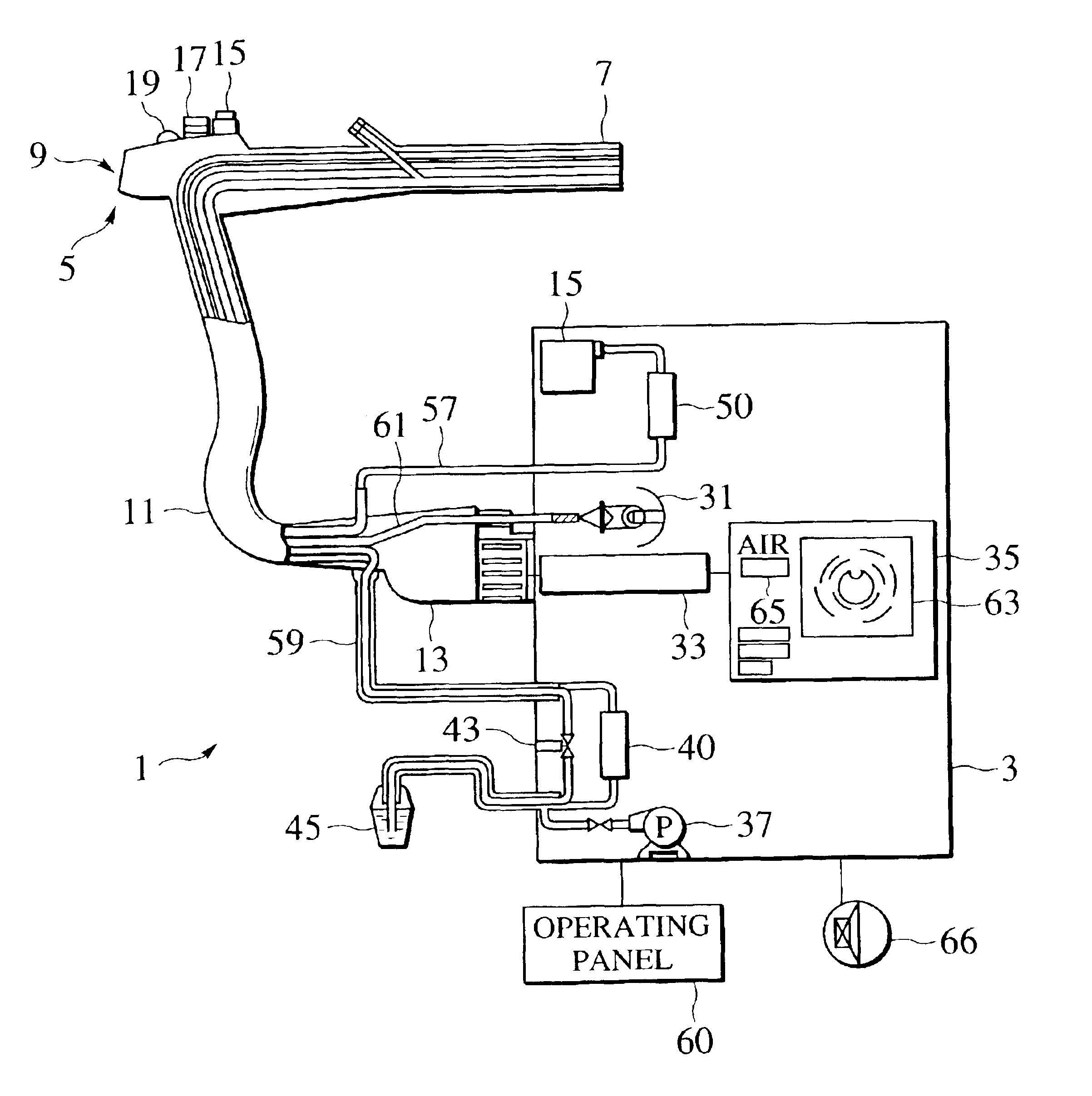
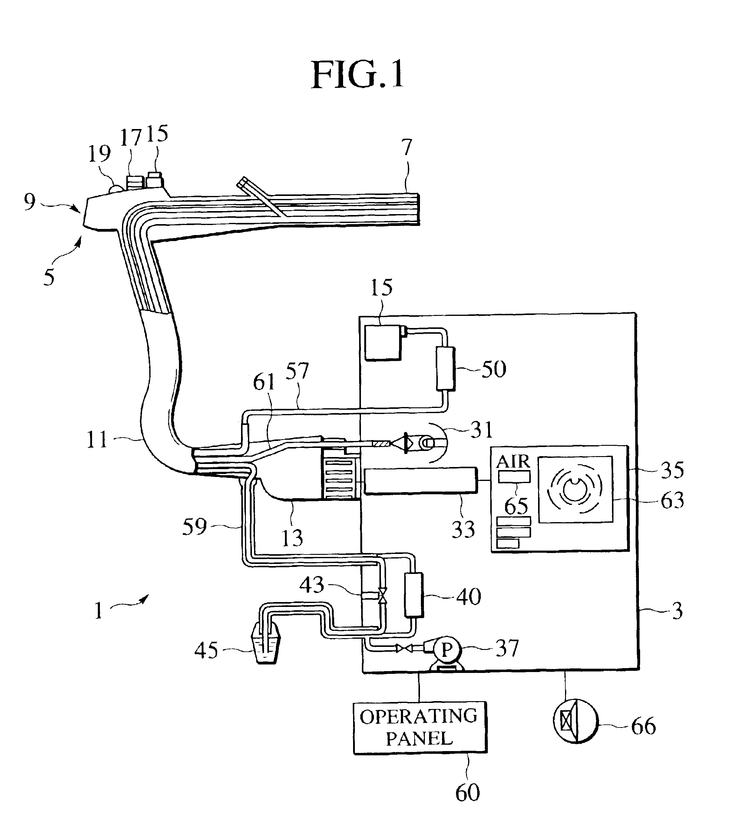
[0024]FIG. 1 shows the configuration of an endoscope apparatus 1 according to the present invention, in which the endoscope apparatus 1 has an endoscope apparatus main unit 3 and an endoscope 5.

[0025]The endoscope 5 has an insertion part 7, the tip of which is fitted with an optical system and imaging element (not shown in the drawing), and which is inserted into a body cavity of the subject being examined, an operation section 9, which is continuous with the rear end of the insertion part 7, a universal cord 11 for the purpose of connecting the operating section 9 to the endoscope apparatus main unit 3, and a connector 13, which is provided on the end of the universal cord 11. The insertion part 7 includes a fluid feed channel through which water or air is fed into the body cavity and a suction channel through which fluid is sucked from the body cavity.

[0026]The operating section 9 has an air / water feed switch 15, which controls the feed of air and water, a suction switch 17, which...

second embodiment

[0064]FIG. 6 is an exploded perspective view showing the main part of an endoscope apparatus according to the present invention, this drawing showing the structure of a suction valve that is provided at the front panel of the endoscope apparatus main unit. In this embodiment, the leakage sound of an electrically controlled suction force control valve can be heard directly by an operator.

[0065]In FIG. 6, the suction force control valve 50 is driven by a motor 309.

[0066]In FIG. 6, the rear surface of the valve case 302 is provided with a depression 306 having the shape of a short cylinder, the front surface being provided with a suction fitting for connection with a suction device (not shown in the drawing), an endoscope fitting 304 for connection with an endoscope (not shown in the drawing), and a leakage nozzle 305. The suction fitting 303, the endoscope fitting 304, and the leakage nozzle 305 are communicate with the depression 306 at the rear of the valve case 302.

[0067]The depres...


PUM


Abstract

In an endoscope apparatus, an air/water switch (15) that is provided in an operating section (9) of an endoscope (5) each generate an air feed on/off signal and a suction on/off signal, and air feed flow and suction flow signals that are responsive to the amount of depression of each of the switches, these signals being sent to a signal processing circuit (33). The signal processing circuit (33) controls a air/water feed control valve 40 and a suction force control valve 50, so as to control air/water feed flow and suction flow, a flow display being made by an indicator (65) on the screen (63) of a TV monitor (35).

Description

CROSS REFERENCE TO RELATED APPLICATIONS[0001]This is a continuation-in-part of application Ser. No. 09 / 392,717, which was filed on Sep. 9, 1999, now abandoned, which is expressly incorporated by reference herein in its entirety.BACKGROUND OF THE INVENTION[0002]1. Field of the Invention[0003]The present invention relates to an endoscope apparatus, and more particularly to an endoscope apparatus which notifies an operator of the flow amounts of such functions as air feed, water feed, and suction.[0004]2. Discussion of Background[0005]As control mechanisms for the functions of water feed, air feed, and suction in an endoscope apparatus for medical use, there exists the mechanical valve system, in which mechanical valves in an operating section are directly pressed, and a solenoid valve system, in which solenoid valves in a processor are controlled by means of signals from control switches in the operating section.[0006]The mechanical valve system is the most commonly used control metho...

Claims


Application Information

Patent Timeline
IPC IPC(8): A61B1/015A61B1/012
CPCA61B1/015
Inventor HIRAKUI, KATSUYASHIGIHARA, AKINORI
Owner KK TOSHIBA
Why Eureka
Try Eureka