Helically formed stent/graft assembly

a graft and helically formed technology, applied in the field of tubular stent/graft assembly, can solve the problems of reduced flexibility, axial stiffness of tubes, and films made into tubes, and achieve the effect of reducing manufacturing costs, consistent wall properties, and no undesired seams, bumps or weak points

Inactive Publication Date: 2005-08-16
BOSTON SCI SCIMED INC
View PDF54 Cites 67 Cited by
  • Summary
  • Abstract
  • Description
  • Claims
  • Application Information

AI Technical Summary

Benefits of technology

[0013]It is a further object of the present invention to provide tubular stent/graft devices that can be manufactured by continuous techniques.
[0014]It is a further object of the present invention to produce the assembly strips in a continuous manufact

Problems solved by technology

With the increased strength, however, often comes reduced flexibility.
While ePTFE has been described above as having desirable biocompatibility qualities, tubes comprised of ePTFE, as well as films made into tubes, tend to exhibit axial stiffness, and minimal ra

Method used


Image

  • Helically formed stent/graft assembly
  • Helically formed stent/graft assembly
  • Helically formed stent/graft assembly

Examples


first embodiment

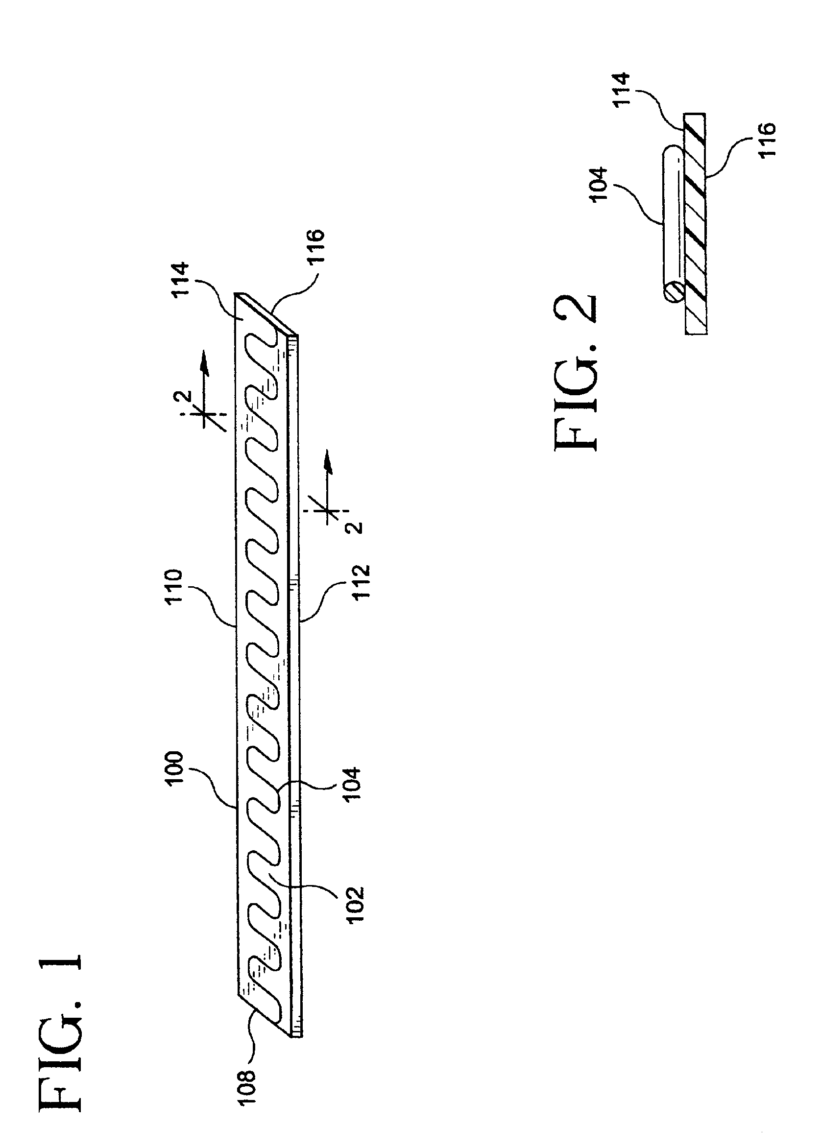
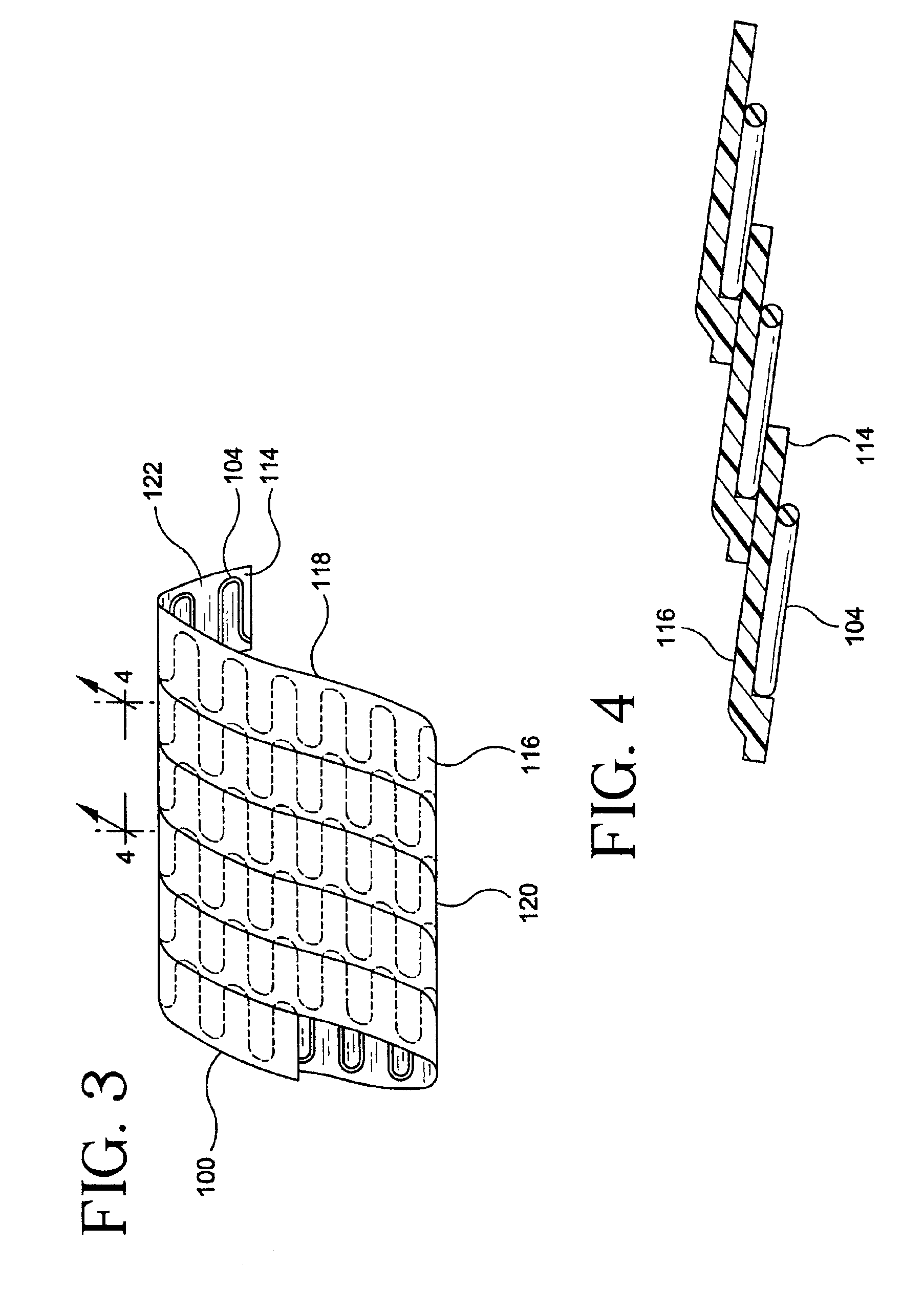
[0056]FIGS. 1 and 2 depict a strip assembly 100 for forming a tubular stent / graft apparatus of the present invention. Strip assembly 100 comprises of a planar graft strip 102 and a planar undulating wire 104. Strip assembly 100 can be formed into a tubular structure by helically winding the strip assembly 100 on a mandrel. Planar wire 104 provides, among other things, support of the graft strip 102 for use as an intraluminal device.

[0057]Assembly strips of the present invention can be produced by continuous manufacturing techniques. Long strips of the assembly strips can be cut to form the desired size of the stent / graft assembly.

[0058]As used herein, the term “wire” shall refer to stent material of a slender shape with various defined cross-sections having a cross-sectional dimension substantially less than the length of the slender shape. Such cross-sections are not limited to spherical shapes, but other shapes, such as, but not limited to, rectangular, square and oval, may suitab...

second embodiment

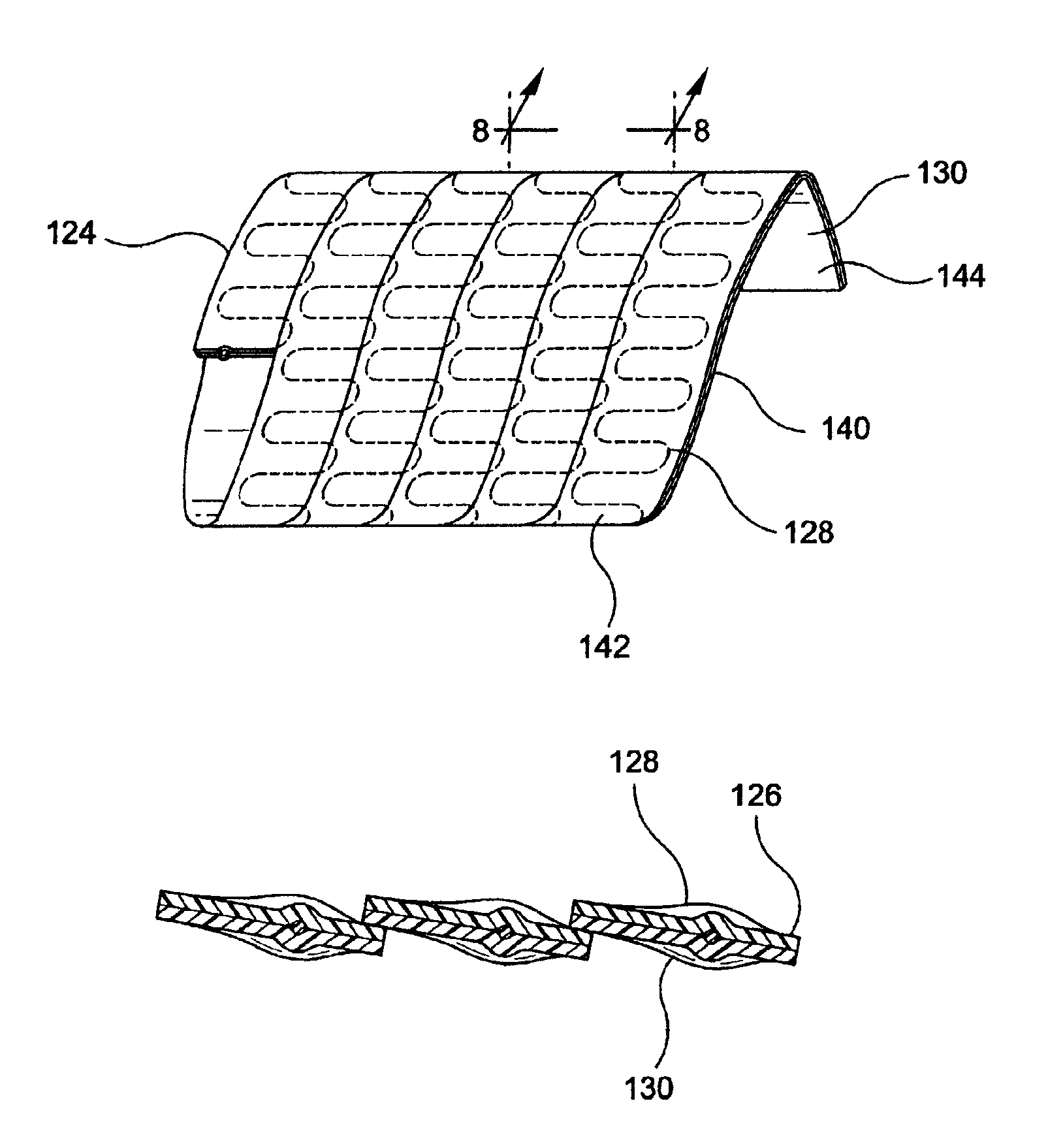
[0063]FIGS. 5 and 6 depict an assembly strip 124 for use as an intraluminal device. Assembly strip 124 comprises planar wire 126 disposed between planar graft strips 128 and 130. Planar graft strips 128 and 130 are composed of the same material as graft material 102. Planar wire 126 undulates between planar graft strips 128 and 130 along the length of said strips therebetween. Planar wire 126 is essentially planar to graft strips 128 and 130. The planar graft strips 128 and 130 may consist of multiple layers of graft material that have been laminated together to form a graft strip thereof.

[0064]Side portion 136 of planar graft strip 128 abuts side portion 138 of planar graft strip 130 along a lengthwise portion of assembly strip 124 to permit formation of a first seam on one side of assembly strip 124. Similarly, side portion 132 of planar graft strip 128 abuts side portion 134 of planar graft strip 130 to permit formation of a second seam on the other side of assembly strip 124. Su...


PUM

PropertyMeasurementUnit
Lengthaaaaaaaaaa
Structureaaaaaaaaaa

Abstract

The present invention relates to a support structure/membrane composite device which includes a support structure, such as a radially expandable stent, a porous non-textile polymeric membrane adjacent to said stent and a thermoplastic anchor means attaching said stent to said porous non-textile polymeric membrane. The porous non-textile polymeric membrane is preferably made from expandable fluoropolymer materials. The anchoring means is a thermoplastic material which is dissolvable at the interface between the support structure and membrane by a suitable solvent which wets the membrane surface and deposits the thermoplastic material within the pores of the membrane. Methods of preparing the device are also disclosed.

Description

CROSS-REFERENCE TO RELATED APPLICATIONS[0001]This application is a divisional of application Ser. No. 09 / 345,026, filed Jul. 2, 1999, now U.S. Pat. No. 6,364,904, the contents of which is incorporated by reference herein.FIELD OF THE INVENTION[0002]The present invention relates to a tubular stent / graft apparatus. More particularly, the present invention relates to a composite intraluminal device including a helically formed tubular stent / graft assembly formed from a planar pre-assembly having a wire stent material laminated between ePTFE strips.BACKGROUND OF THE INVENTION[0003]An intraluminal prosthesis is a medical device commonly known to be used in the treatment of diseased blood vessels. An intraluminal prosthesis is typically used to repair, replace, or otherwise correct a damaged blood vessel. An artery or vein may be diseased in a variety of different ways. The prosthesis may therefore be used to prevent or treat a wide variety of defects such as stenosis of the vessel, throm...

Claims


Application Information

Patent Timeline
IPC IPC(8): A61F2/06A61F2/88
CPCA61F2/07A61F2/88A61F2002/072A61F2002/075A61F2220/0058A61F2220/0075
Inventor SMITH, SCOTT
Owner BOSTON SCI SCIMED INC
Why Eureka
Try Eureka