Vaporizer tube for vaporizing liquid samples in capillary gas chromatography

a technology of liquid sample and vaporizer tube, which is applied in the direction of withdrawing sample devices, component separation, water/sludge/sewage treatment, etc., can solve the problem of impeded focus of packed columns

Inactive Publication Date: 2005-08-16
JOINT ANALYTICAL SYST
View PDF2 Cites 5 Cited by
  • Summary
  • Abstract
  • Description
  • Claims
  • Application Information

AI Technical Summary

Benefits of technology

[0009]It is a more specific object of the invention to volatilize and remove the solvent without impeding the focusing of the sample proper at the inlet of a capillary column.
[0010]To this end, the vaporizer tube is open throughout its whole length for the passage of the sample and of a carrier gas flow. The vaporizer tube has throat means, which are so designed as to heavily increase the flow velocity therein and, thereby, generating reduced pressure.

Problems solved by technology

Such focusing is impeded by packed columns as pre-separators.

Method used


Image

  • Vaporizer tube for vaporizing liquid samples in capillary gas chromatography
  • Vaporizer tube for vaporizing liquid samples in capillary gas chromatography
  • Vaporizer tube for vaporizing liquid samples in capillary gas chromatography

Examples


Embodiment Construction

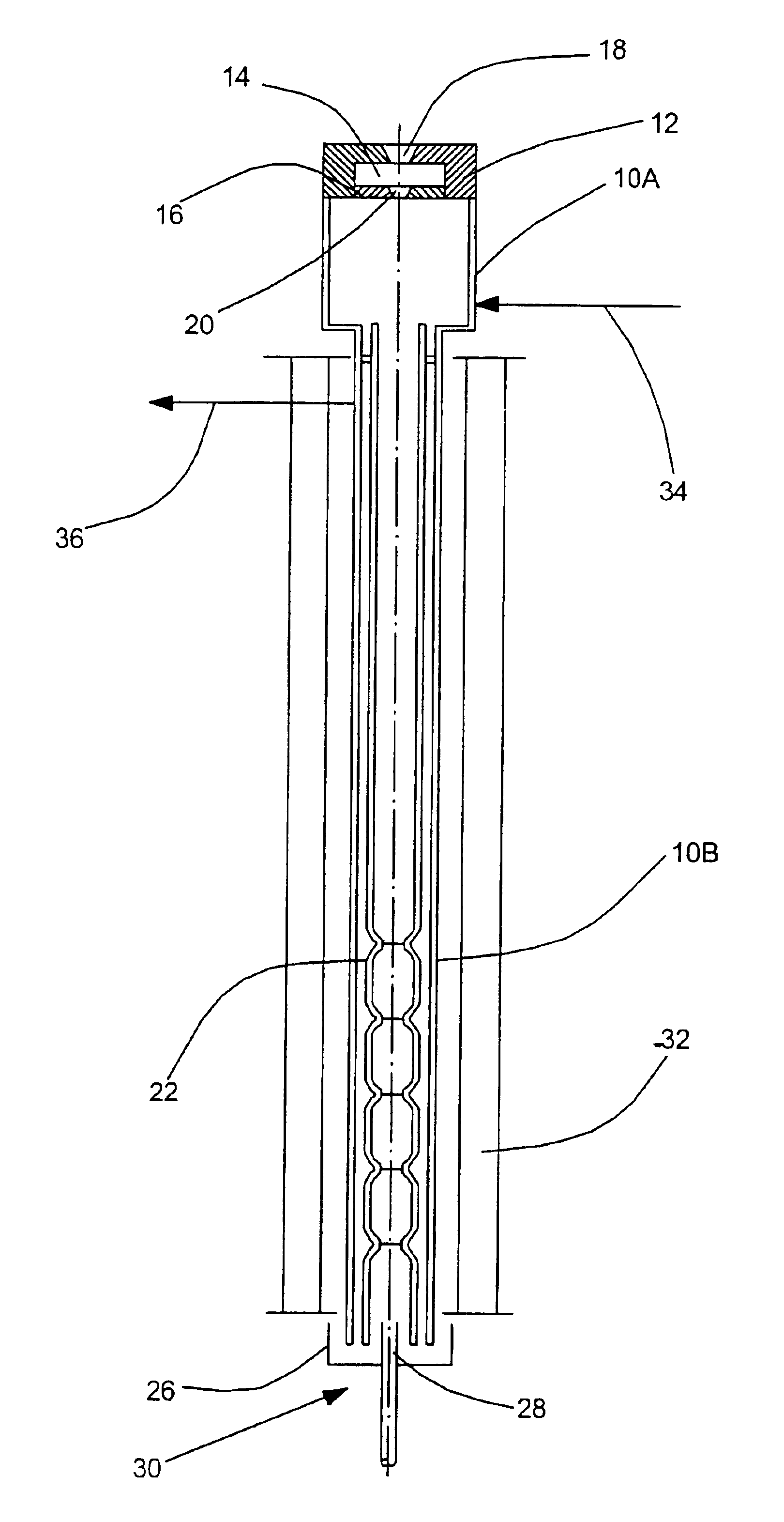
[0018]Referring to FIG. 1, numeral 10 designates a sample inlet chamber. The sample inlet chamber 10 is closed at its upper end by a cap 12, which holds a septum 14. The septum 14 is supported by a plate 16. The cap 12 has a conical aperture 18 tapering towards the septum. The plate 16 has an aperture 20 aligned with the aperture 18 and tapering towards the bottom of FIG. 1. The sample inlet chamber 10 has a larger diameter, cylindrical upper portion 10A and an adjacent lower portion 10B of reduced diameter.

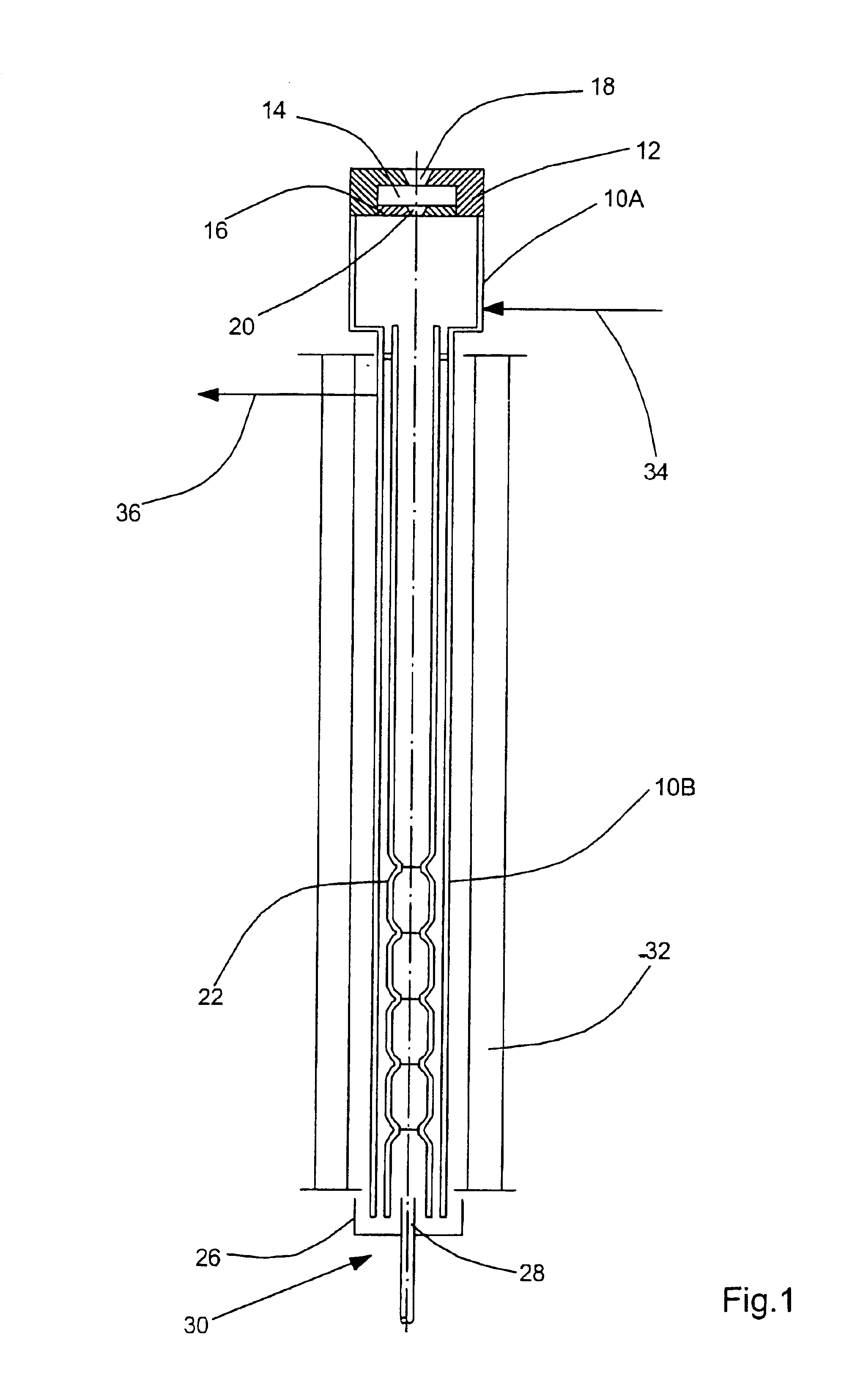
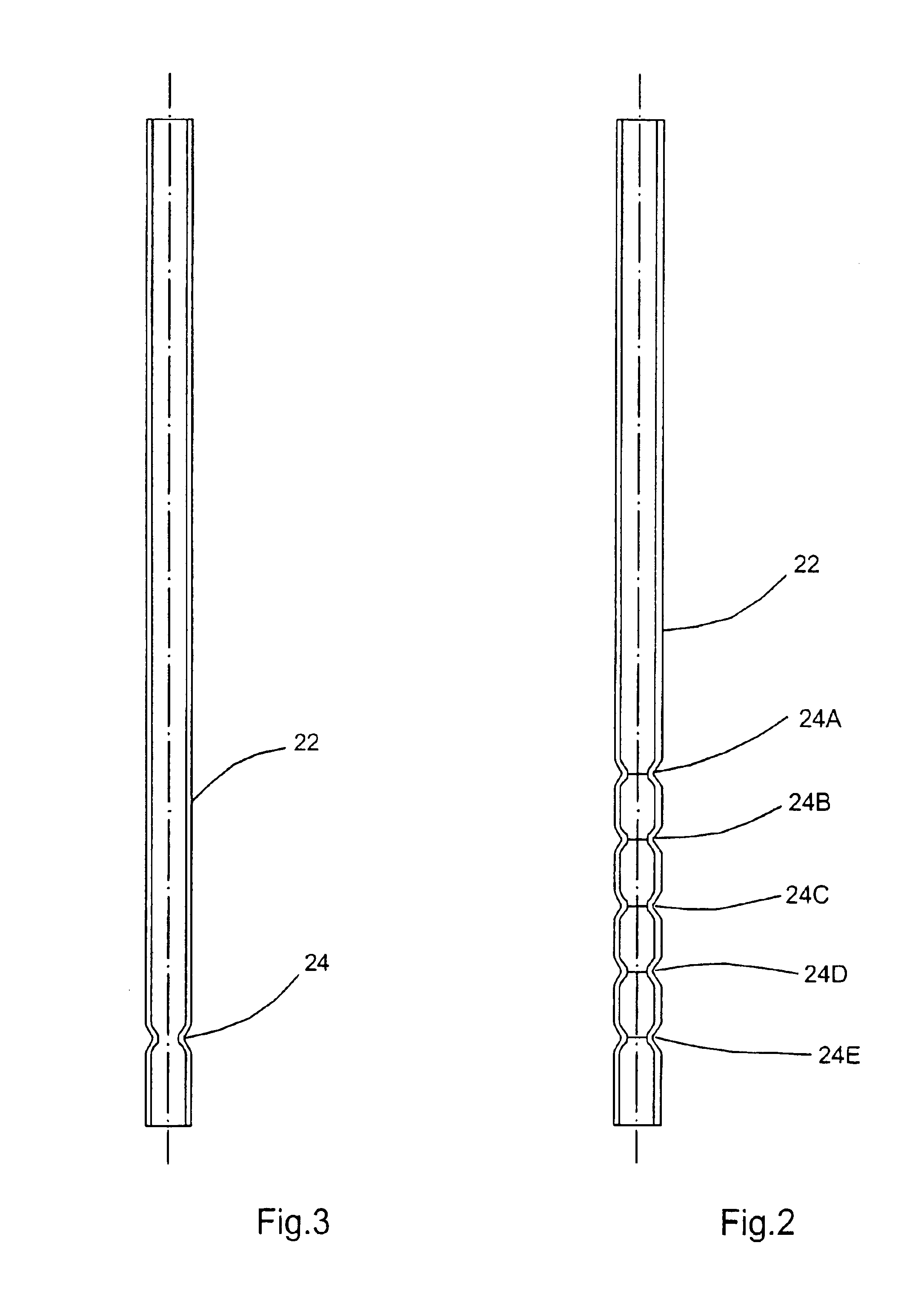
[0019]A vaporizer tube 22 is retained coaxial in the sample inlet chamber. The vaporizer tube 22 is shown in detail in FIG. 2. The vaporizer tube 22 consists of an inert material such as glass or quartz. The vaporizer tube 22 has a sequence of equally spaced throats 24A, 24B, 24C, 24D and 24E. Each of the throats is shaped like a Venturi tube. In the region of each of the throats, the flow velocity of the medium flowing through the vaporizer tube is substantially increased. Accor...


PUM

PropertyMeasurementUnit
inner diameteraaaaaaaaaa
velocityaaaaaaaaaa

Abstract

The invention relates to a vaporizer tube for vaporizing liquid samples in capillary gas chromatography. The vaporizer tube is open throughout its whole length. It has throats which are shaped to provide, in their region, a heavy increase of the flow velocity of the carrier gas, which flows substantially unrestrictedly through the vaporizer tube. This increase of the flow velocity causes, in accordance with Bernoulli's law, reduction in pressure. Due to this pressure reduction, the easily volatile solvent is predominantly volatilized. This vaporized solvent is carried along by the carrier gas flow. The solvent can then be removed through an outlet of the sample inlet chamber. The sample proper is vaporized in the larger diameter, low velocity zones between the throats by heating the vaporizer tube and are fed to the capillary column, after the solvent has been volatilized. Thus the vaporizer tube with a plurality of throats acts like a multi-plate column.

Description

[0001]The invention relates to a vaporizer tube for vaporizing liquid samples in capillary gas chromatography.BACKGROUND OF THE INVENTION[0002]Gas chromatography is a method of separating substance mixtures. A sample of the substance mixture is vaporized. The vapor is “flushed”, by means of an inert carrier gas flow, through a separating column filled with a separating substance. The various substances or components of the substance mixture will migrate through the separating column at different velocities, depending on their affinity to the separating substance such as the solubility in a liquid separating substance. The components of the sample fed to the inlet of the column together as a “plug”, will appear at different times consecutively at the outlet of the column and will be detected by a detector responding to such components. When such component emerges from the column, the detector provides a “peak”, i.e. for example, a tooth or bell shaped signal.[0003]So-called “capillar...

Claims


Application Information

Patent Timeline
Patent Type & Authority Patents(United States)
IPC IPC(8): G01N30/00G01N30/12
CPCG01N30/12Y10T436/25875
Inventor GERSTEL, JOACHIM
Owner JOINT ANALYTICAL SYST
Why Eureka
Try Eureka