
Printable assist lines and the removal of such

a technology of assist lines and printing, applied in the direction of instruments, photomechanical devices, relative volume flow measurements, etc., can solve the problem of limited methods and achieve the effect of narrowing the range of the distribution of line-to-space ratio

Inactive Publication Date: 2005-08-16
TAIWAN SEMICON MFG CO LTD
View PDF7 Cites 28 Cited by
  • Summary
  • Abstract
  • Description
  • Claims
  • Application Information

AI Technical Summary

Benefits of technology

[0011]Another objective of the invention is to narrow the range of the distribution of the line-to-space ratio in a given mask pattern that is used for photolithographic exposure.

Problems solved by technology

This method is therefore limited by the small size of the scattering bars.

Method used


Image

  • Printable assist lines and the removal of such
  • Printable assist lines and the removal of such
  • Printable assist lines and the removal of such

Examples


Embodiment Construction

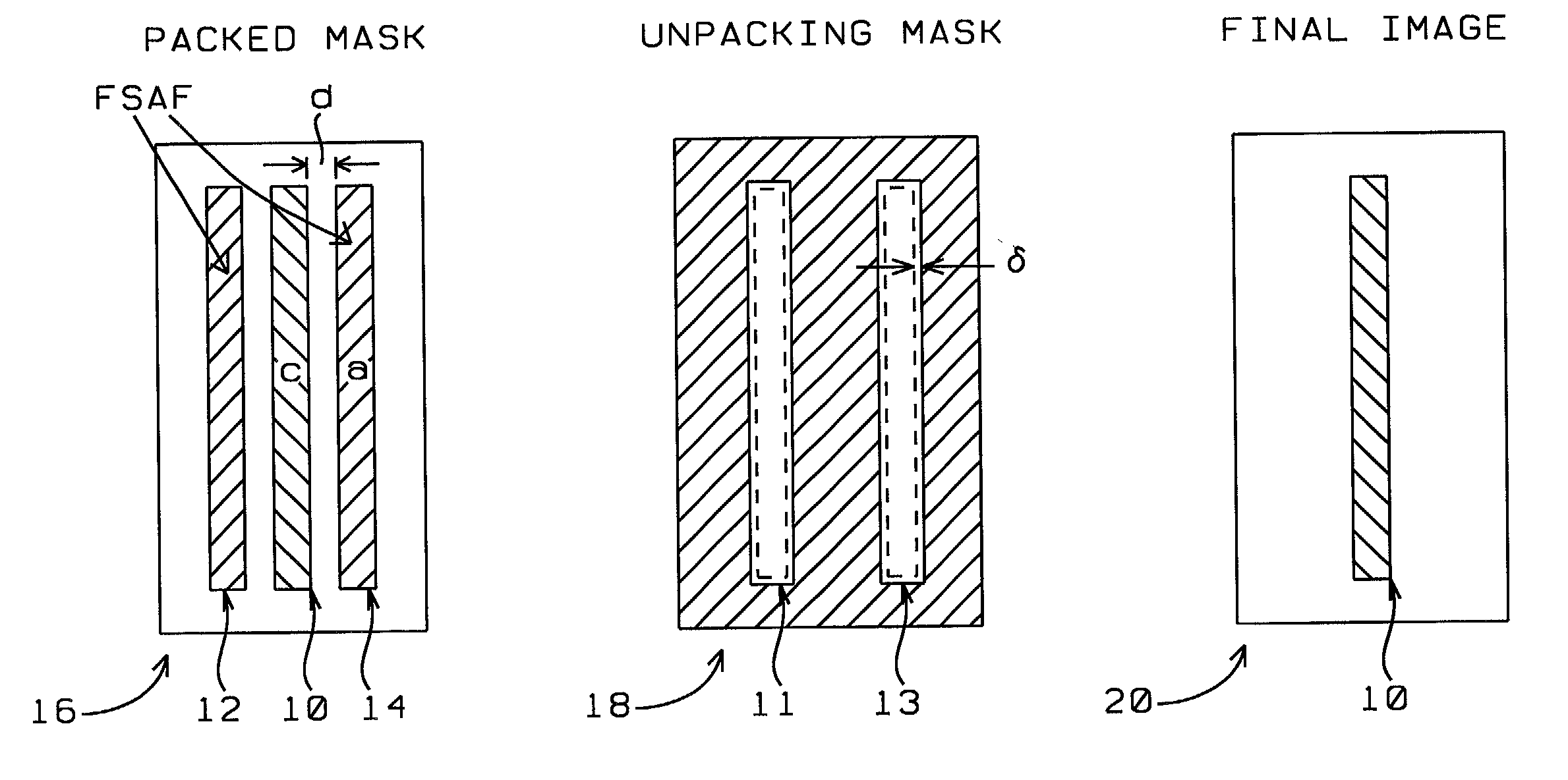
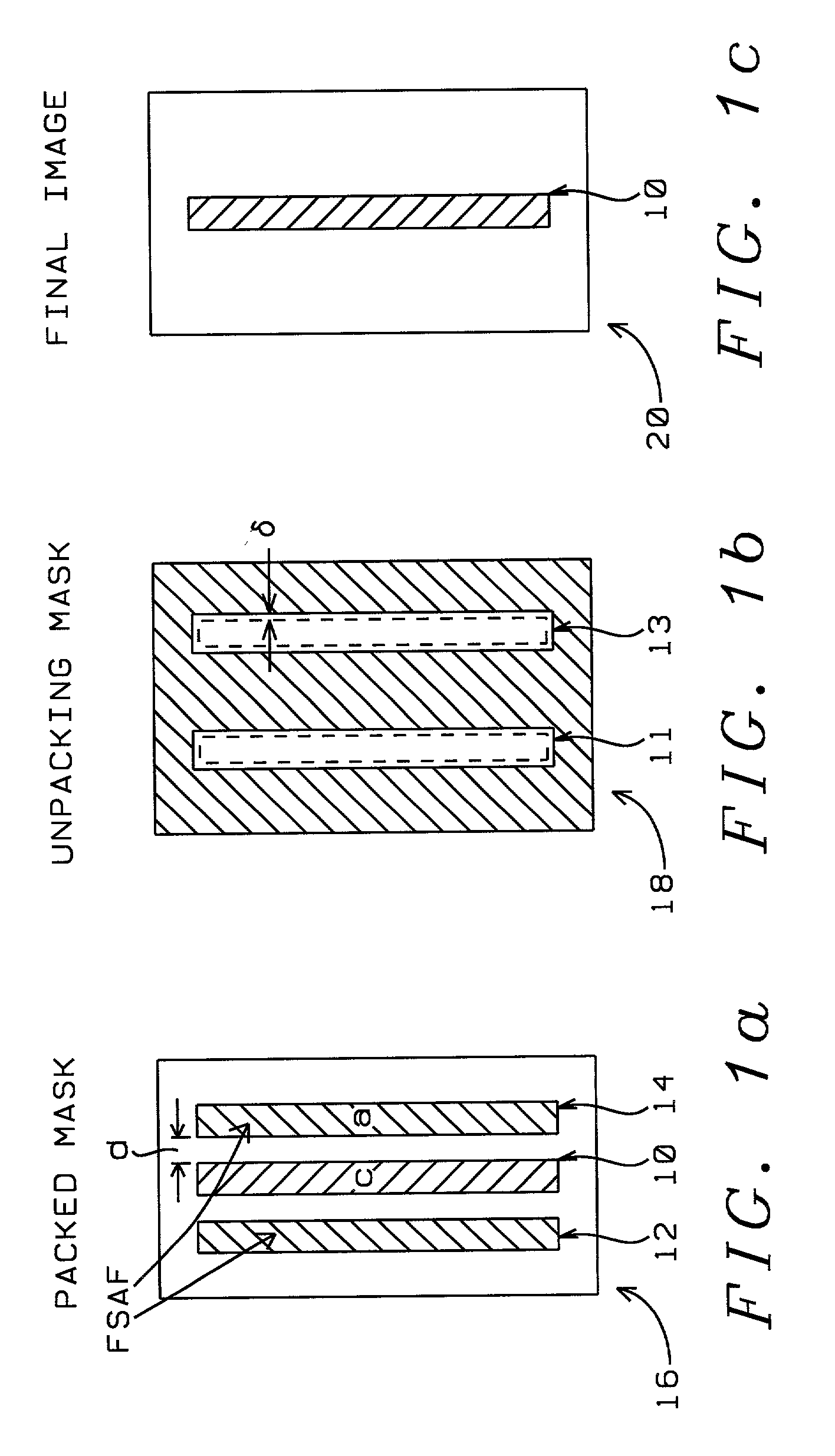
[0027]As has been previously highlighted, close line spacing in the range of a line-width to line-spacing (L / S) ratio of 1:1 is difficult to achieve for devices having resolution-limiting size, resulting in a narrow latitude of exposure and a small depth of focus or both. To correct this problem, a well-known method is to use off-axis illumination, in the form of annular, quadruple or dipole configurations. A limitation of this method is that the location of the ring, quadruples or dipoles can be optimized only for a special frequency in the object. For example, only the image of pairs of 1:1 spaced lines (line-width to line-spacing ratio) can be optimized. In this case of optimization, lines with a L:S=1:2 ratio will benefit less from this optimization scheme, lines that are spaced further apart benefit even less. This scheme can be applied to lines with for instance L:S=1:2 but this optimization is achieved at the expense of lines with higher and lower ratios of L:S.

[0028]A freque...


PUM

PropertyMeasurementUnit
sizeaaaaaaaaaa
dimensionsaaaaaaaaaa
distanceaaaaaaaaaa

Abstract

A new method of applying FSAF is provided that optimizes the distribution of the spatial frequency and the unification of the photolithographic exposure level. The FSAF are removed by an additional exposure, using a specially designed mask that contains erasing features at the location of the FSAF.

Description

BACKGROUND OF THE INVENTION[0001](1) Field of the Invention[0002]The invention relates to the fabrication of integrated circuit devices, and more particularly, to a method to further improve the imaging of patterns that are used in photolithography by providing improved enhancement effects for sub-resolution lines that are added to a line pattern, to address issues of having insufficient space in order to add sub-resolution lines and issues of avoiding printing sub-resolution lines.[0003](2) Description of the Prior Art[0004]The creation of semiconductor devices requires numerous interacting and mutually supporting disciplines. Addressed at this time are the disciplines that are required to create patterns on a semiconductor surface, such as the surface of a layer of photoresist or the surface of a semiconductor substrate.[0005]Since device features are transposed from a mask onto a semiconductor surface using photolithographic imaging processes, which requires the transfer of photo...

Claims


Application Information

Patent Timeline
Patent Type & Authority Patents(United States)
IPC IPC(8): G03F7/20
CPCG03F7/70433G03F7/70441
Inventor LIN, BURN-JENGLIU, RU-GYNHWANG, GUE WUU
Owner TAIWAN SEMICON MFG CO LTD
Features
  • Generate Ideas
  • Intellectual Property
  • Life Sciences
  • Materials
  • Tech Scout
  • Unparalleled Data Quality
  • Higher Quality Content
  • 60% Fewer Hallucinations
Learn More