Filter

a filter and filter technology, applied in the field of high-precision filters, can solve the problems of difficult to realize characteristics, characteristic frequency or selectivity also deviating from ideal characteristics, used for phase advance elements, etc., and achieves the effect of sufficient attenuation of notch filters, high accuracy, and strong resistance to variations

Inactive Publication Date: 2005-08-16
PANASONIC CORP
View PDF4 Cites 20 Cited by
  • Summary
  • Abstract
  • Description
  • Claims
  • Application Information

AI Technical Summary

Benefits of technology

[0076]According to this configuration, the fourth and the fifth full differential transconductance circuit which perform the voltage-current conversion of the difference between the voltage of the positive phase filter input terminal and the voltage of the negative phase filter input terminal, and the sixth and the seventh full differential transconductance circuit which perform the voltage-current conversion of the difference of the voltage of the positive phase filter output terminal and the voltage of the negative phase filter output terminal are added to the second integrator so that the output current of the fourth and the sixth full differential transconductance circuit is added to the output current of the third full differential transconductance circuit with positive polarity, and the output current of the fifth and the seventh full differential transconductance circuit is added to the output current of the third full differential transconductance circuit with reversed polarity. Therefore, by adjusting the fourth, the fifth, the sixth, or the seventh full differential transconductance circuit, eve

Problems solved by technology

In particular, in a steep filter having high selectivity, or a notch filter having a large attenuation, the deviation has become larger, and that has made it difficult to realize the characteristics.
In addition, a characteristic frequency or selectivity also deviates from ideal characteristics.
However, when the transconductance circuit which comprises of a transistor is compensated by a pure resistance, a p

Method used


Image

  • Filter
  • Filter
  • Filter

Examples


first embodiment

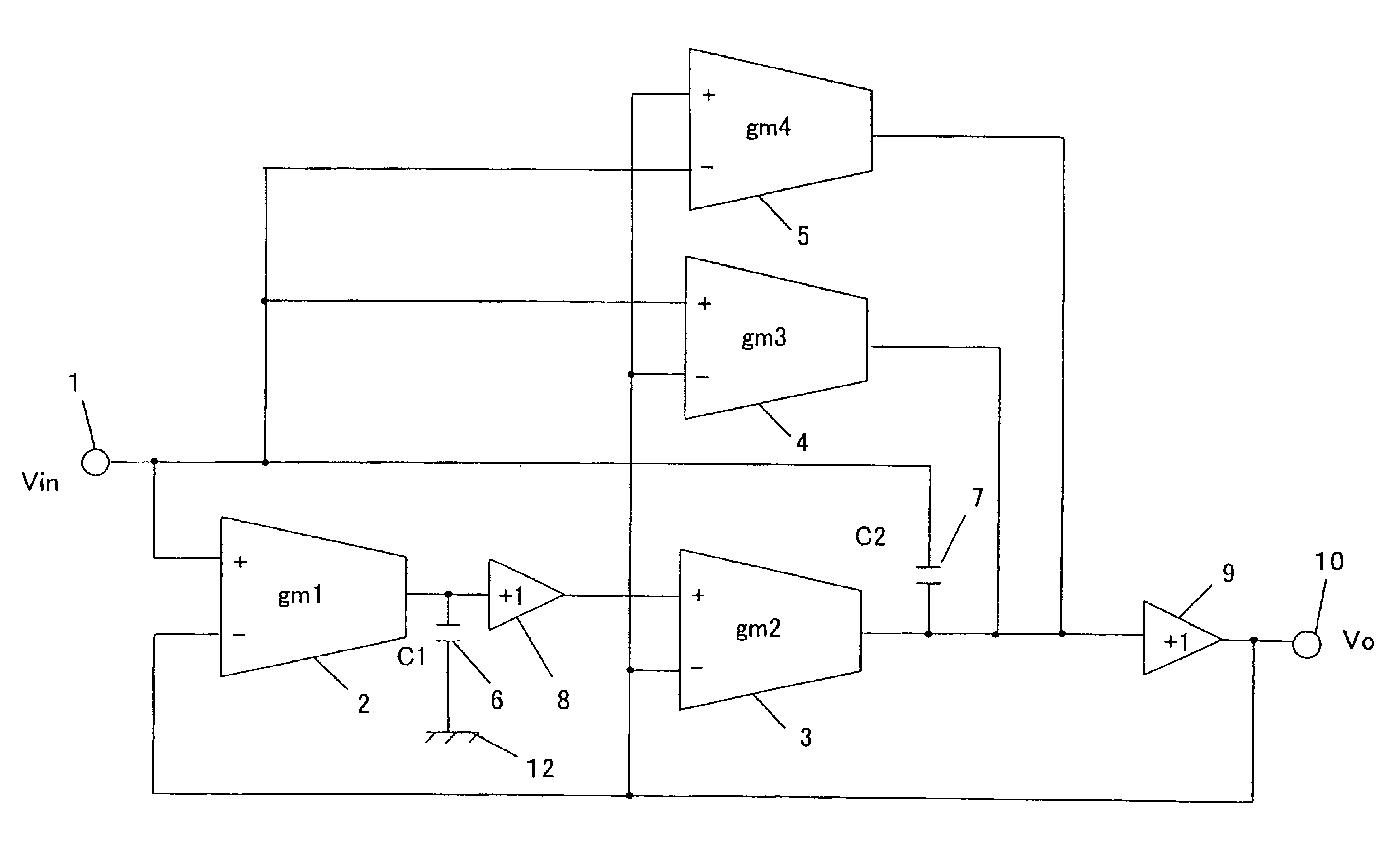
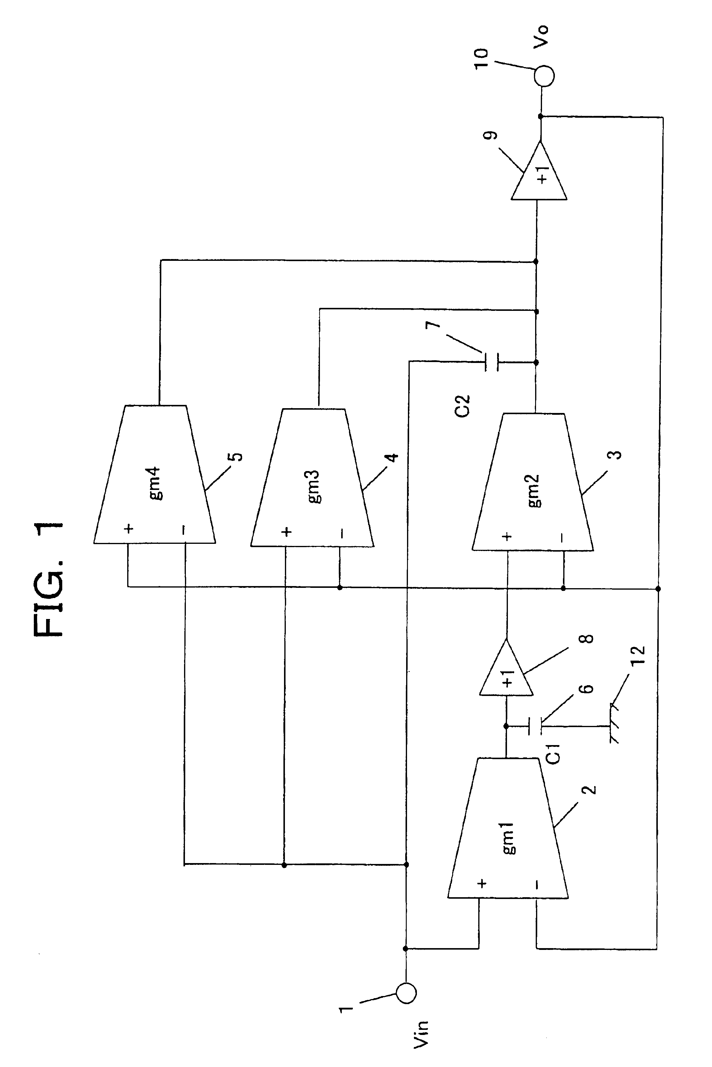
[0099]As described above, according to the present invention, the transconductance circuits 4 and 5 which perform a voltage-current conversion of a difference between a voltage of the filter input terminal 1 and a voltage of the filter output terminal 10 are arranged so that an output current of the transconductance circuit 4 is added to an output current of the transconductance circuit 3, and an output current of the transconductance circuit 5 is subtracted from the output current of the transconductance circuit 3. Therefore, by adjusting the transconductance circuits 4 or 5, even when non-ideal characteristics would exist in the transconductance circuits 2 or 3, those can be canceled, and thereby desired characteristics of the filter, such as a notch filter, an all-pass filter, a bell filter, a dip filter or the like, can be obtained with high accuracy, and a filter which is strong against variations in elements can be obtained. In particular, even when the non-ideal characteristi...

second embodiment

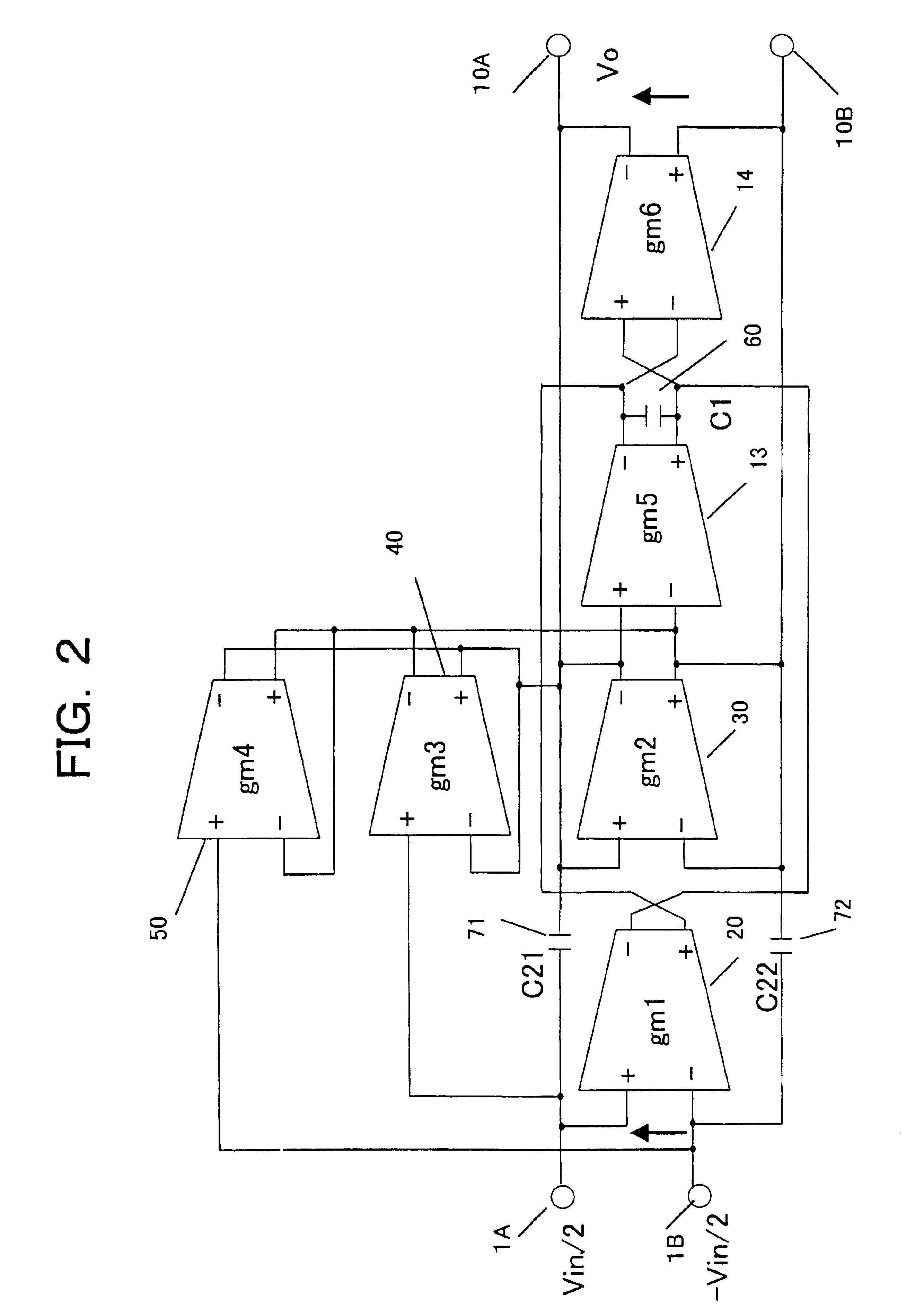
[0103]A second embodiment according to the present invention is shown in FIG. 2. In FIG. 2, reference numeral 1A represents a positive phase filter input terminal, reference numeral 1B represents a negative phase filter input terminal, reference numerals 20, 30, 40, 50, 13, and 14 represent full differential transconductance circuits, respectively, and reference numerals 60, 71, and 72 represent capacitors, respectively. Except that the full differential transconductance circuits 40 and 50 which have transconductance values gm3 and gm4, respectively, are added, it is the same as that of a prior art in FIG. 6.

[0104]Supposing that transconductance values of transconductance circuits 20, 30, 40, 50, 13, and 14 are gm1, gm2, gm3, gm4, gm5, and gm6, respectively, a capacitance value of capacitor 60 is C1, capacitance values of capacitors 71 and 72 are C21 and C22, respectively, and C21=C22=C2, a transfer function H(s) of this circuit becomes as follows. That is, the transfer function H (...

third embodiment

[0111]A third embodiment according to the present invention is shown in FIG. 3. In FIG. 3, reference numeral 1A represents a positive phase filter input terminal, reference numeral 1B represents a negative phase filter input terminal, reference numerals 20, 30, 40, 50, 13, 14, 18, and 19 represent full differential transconductance circuits, respectively, and reference numerals 60, 71, and 72 represent capacitors, respectively. Except that the full differential transconductance circuits 40, 50, 18, and 19 are added, it is the same as that of the prior art in FIG. 6.

[0112]Supposing that transconductance values of transconductance circuits 20, 30, 40, 50, 13, 14, 18, and 19 are gm1, gm2, gm3, gm4, gm5, gm6, gm7, and gm8, respectively, a capacitance value of a capacitor 60 is C1, capacitance values of capacitors 71 and 72 are C21 and C22, respectively, and C21=C22=C2, a transfer function H(s) of this circuit becomes as follows. That is, the transfer function H (s) is H⁡(s)=⁢Vo / Vin=⁢(s2...


PUM


Abstract

The object of the present invention is to obtain a high precision notch filter or all-pass filter. Therefore, two transconductance circuits for adjustment, which perform a voltage-current conversion of a difference between a voltage of a filter input terminal and a voltage of a filter output terminal, are added to two integrators comprising two transconductance circuits for the integrators, and two capacitors. An output current of one transconductance circuit for adjustment is added to an output current of the transconductance circuit for the integrators, and an output current of the other transconductance circuit for adjustment is subtracted from an output current of the transconductance circuit for the integrators. Therefore, by adjusting conductance values of the two transconductance circuits for adjustment, even when non-ideal characteristics would exist in the transconductance circuits for the integrators, those can be canceled.

Description

BACKGROUND OF THE INVENTION[0001]1. Field of the Invention[0002]The present invention relates to a high precision filter used in a communication field or the like. In particular, it relates to a notch filter which can control an attenuation.[0003]2. Prior Art[0004]FIG. 4 is a block diagram showing one example of a notch filter circuit which is used in a prior art, and shows a biquad-type second order notch filter configuration. In FIG. 4, reference numeral 1 represents an input terminal to which an input voltage Vin is inputted. Reference numerals 2 and 3 represent transconductance circuits which have transconductance values gm1 and gm2, respectively. Reference numerals 8 and 9 represent voltage buffer circuits, respectively. Reference numerals 6 and 7 represent capacitors which have capacitance values C1 and C2, respectively. Reference numeral 12 represents a ground terminal. Reference numeral 10 represents a filter output terminal from which an output voltage Vo is outputted.[0005...

Claims


Application Information

Patent Timeline
IPC IPC(8): H03H11/04
CPCH03H11/04
Inventor YOKOYAMA, AKIO
Owner PANASONIC CORP
Why Eureka
Try Eureka