Video appliance, holding device, and manufacturing method of holding device

Inactive Publication Date: 2005-08-16
PANASONIC CORP
View PDF17 Cites 4 Cited by
  • Summary
  • Abstract
  • Description
  • Claims
  • Application Information

AI Technical Summary

Benefits of technology

[0020]The rib section having the groove of the gutter is more rigid than a flat plate shape, and has a reduced wall thickness. And the rib section has a low material cost.
[0021]Moreover, as the degaussing coil in the groove, the rib section can hold the coil without other parts than the holding device for hold

Problems solved by technology

1) Generally, the case for the video appliance such as television receiver is composed of two members, that is, a front cover (front case) for mounting the display panel such as CRT, and a rear cover (rear case) for covering the rear part of the display panel. The rear cover is shaped like a container, and as the video appliance becomes larger, the projection area of the rear cover becomes wider. For an injection molding of the rear cover, therefore, a molding machine having a large clamping force is required.
2) In the case disclosed in Japanese Laid-open Patent No. 10-336552, the distance form a runner section to a sprue section for pouring me

Method used


Image

  • Video appliance, holding device, and manufacturing method of holding device
  • Video appliance, holding device, and manufacturing method of holding device
  • Video appliance, holding device, and manufacturing method of holding device

Examples


Example

(Embodiment 1)

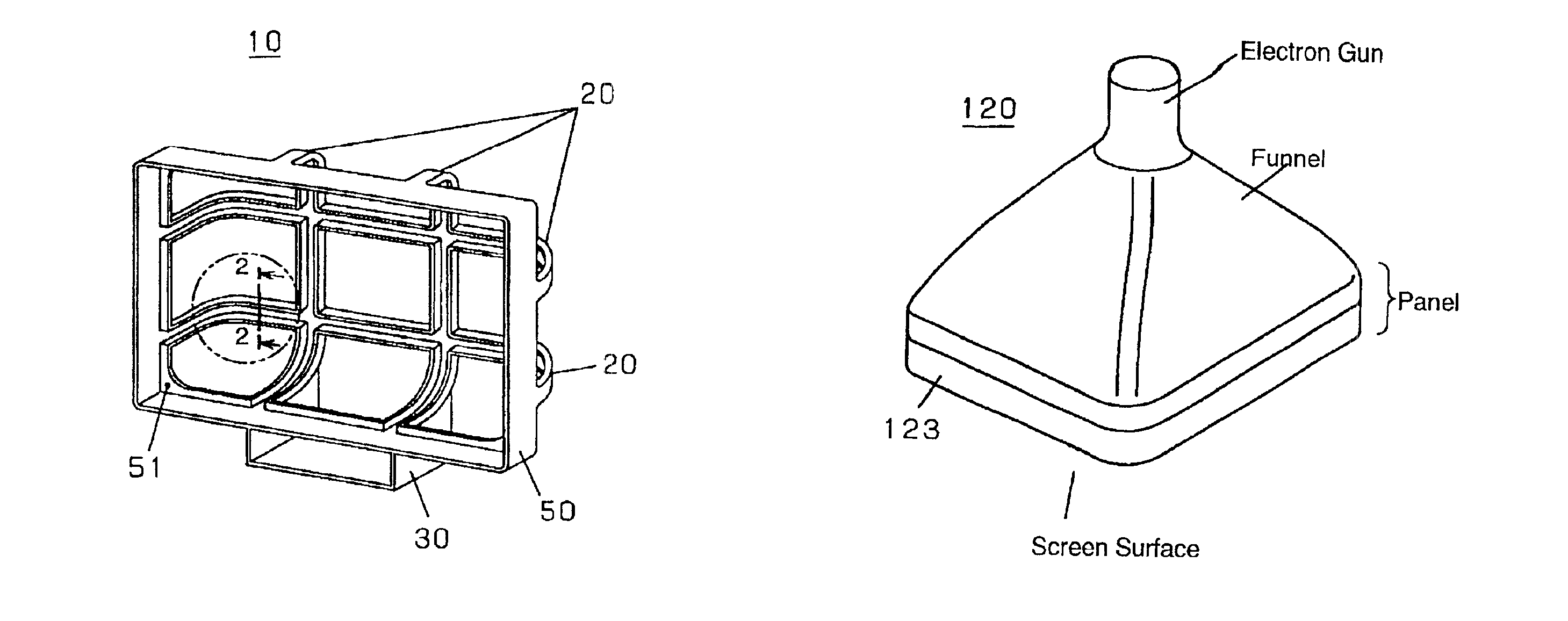
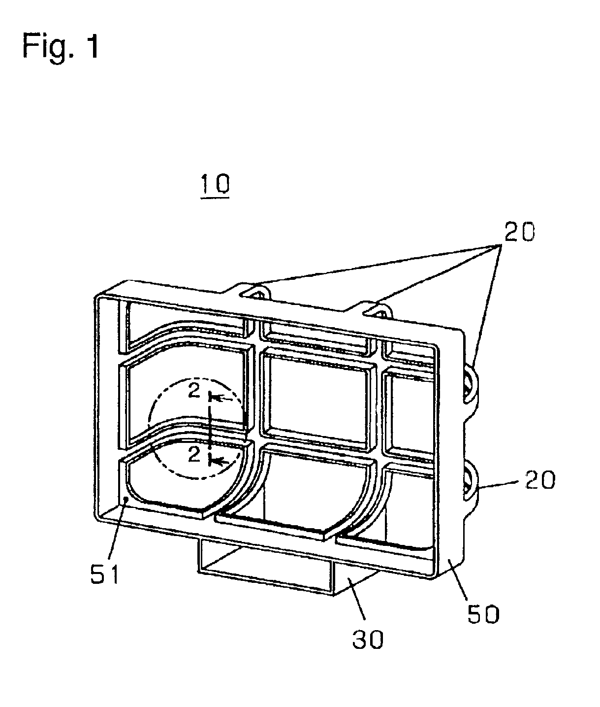
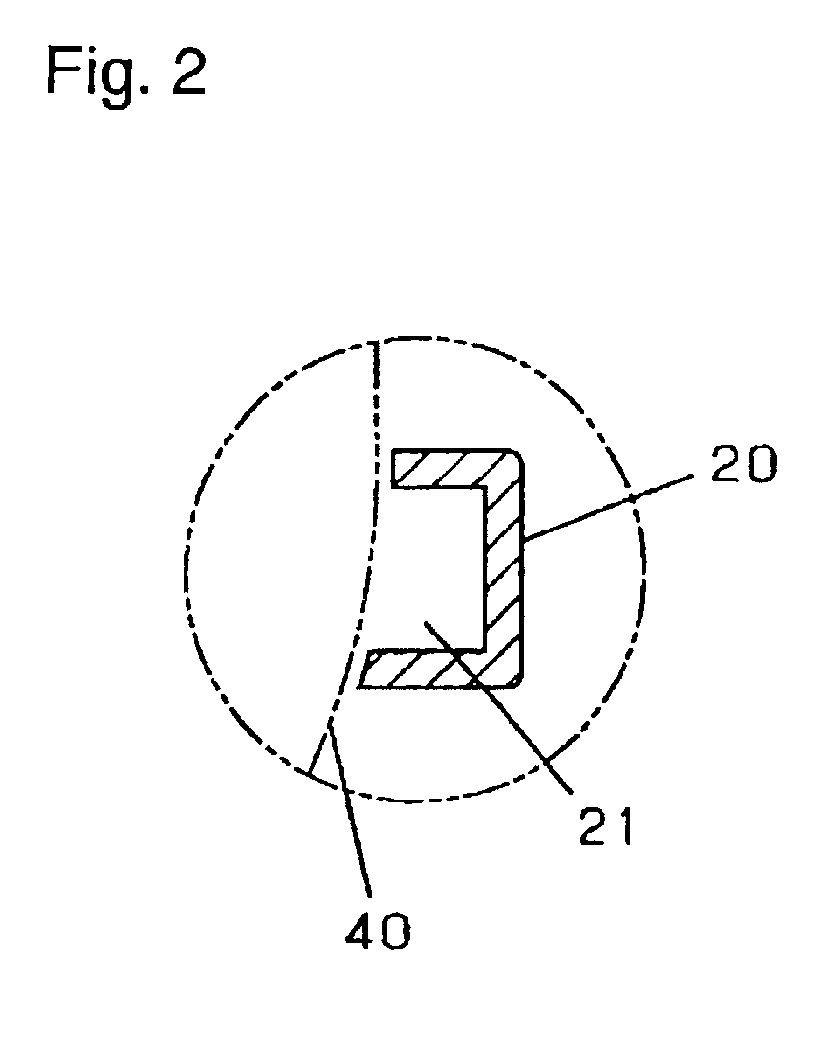
[0035]FIG. 1 shows a display panel holding device according to embodiment 1 of the present invention, and is a perspective outline view of a holding device 10 of a cathode-ray tube (CRT). FIG. 2 is an essential sectional view along a cut line 2—2 in FIG. 1. FIG. 11 is a perspective view of a CRT seen from the rear side for an explanation of the invention. A CRT 120 includes an electron gun, funnel, and panel A metal band 123 is wound around the panel. The funnel is shaped like a quadrangular pyramid. The panel has a screen surface disposed at the viewer side for displaying image by the electron gun.

[0036]As shown in FIG. 1 and FIG. 2, the CRT holding device 10 includes a rib section 20 corresponding to a shape of the funnel of the CRT 120, a rectangular frame 50 corresponding to an outline of the panel, and a support base 30 linked to at least one of the rib section 20 and the frame 60. The CRT holding device 10 holds the CRT 120 from the rear side in self-standing man...

Example

(Embodiment 2)

[0043]FIG. 3 is a perspective view of a television receiver, that is, a video appliance according to embodiment 2 of the present invention. FIG. 4 is a perspective exploded view of the television receiver in FIG. 3. FIG. 5 is a perspective view of the television receiver in FIG. 3 seen from the rear side.

[0044]As shown in FIG. 3 to FIG. 5, the television receiver 100 includes a cathode-ray tube (CRT) 120, a CRT holding device 130 for holding the CRT 120 from the rear side, and a front panel 140 attached to a screen surface 122 of the CRT 120. That is, the CRT holding device 130, which is the same as the CRT holding device explained in embodiment 1, holds the CRT 120 from the rear side in self-standing manner, and the front panel 140 is attached from the screen side of the CRT 120. The television receiver further includes a control circuit, a speaker device, a cover for covering the control circuit, and others as required (not shown). The CRT 120 has a metal band 123 wo...

Example

(Embodiment 3)

[0048]FIG. 6 is a perspective view of a television receiver seen from the rear side according to embodiment 3 of the invention. FIG. 7 is a perspective exploded view showing a process of mounting a degaussing coil in a groove of a CRT holding device included in the television receiver in FIG. 6. FIG. 8 is an essential sectional view along a cut line 8—8 in FIG. 6.

[0049]In FIG. 6 to FIG. 8, a television receiver 200 includes a cathode-ray tube (CRT) 220, a front panel 240 attached to the screen side of the CRT 220, a CRT holding device 230 for holding the CRT 220 from the rear side, and a degaussing coil 210 put in a groove 231 of the CRT holding device 230. That is, this receiver is substantially identical with the television receiver 100 explained in embodiment 2, except that the degaussing coil 210 is disposed in the groove 231 of the CRT holding device 230.

[0050]The degaussing coil 210 is made of a conductor wire turned spirally by a specified number of turns, and i...


PUM


Abstract

A cathode-ray tube (CRT) holding device holds a CRT from the rear side by a rib section having a shape similar to that of a funnel of the CRT and extending in plural directions. The rib section has a section having shaped in a recessed groove, and a degaussing coil is disposed in the groove. The CRT holding device has a low cost and a raised recycling rate. Without increasing the number of parts, the degaussing coil can be mounted.

Description

DESCRIPTION[0001]Video appliance, holding device, and manufacturing method of holding deviceTECHNICAL FIELD[0002]The present invention relates to a holding device for a display panel such as cathode-ray tube (CRT), and a video appliance incorporating the CRT.BACKGROUND ART[0003]In a video appliance, for example, a television receiver and display monitor, an injection molding of metal members to form a case for holding or accommodating a display panel has been proposed to enhance a recycling rate. For example, Japanese Laid-open Patent No. 10-42227 discloses a case formed by the injection molding of metal members made of magnesium alloy or the like. Japanese Laid-open Patent No. 10-336552 proposes an injection molding of a case for a large-sized video appliance with a molding machine having a small clamping force.[0004]Regarding a mounting of a degaussing coil on the CRT, Japanese Laid-open Patent No. 62-85592 and Japanese Laid-open Patent No. 5-284513 discloses, for example, a degau...

Claims


Application Information

Patent Timeline
IPC IPC(8): H04N5/645H01J9/46G09F9/00H04N5/64
CPCH04N5/645Y10S269/903Y10S269/908Y10S269/909
Inventor HIROTA, NARUMIMATSUOKA, YUICHIYAMATO, YASUJI
Owner PANASONIC CORP
Why Eureka
Try Eureka