High current capacitors

a capacitor and high current technology, applied in the field of capacitors, can solve the problems of affecting the ability to detect faults within the capacitor, affecting the production efficiency of capacitors, and catching fire in the apparatus, and achieve the effect of easy manufacturing

Inactive Publication Date: 2005-08-16
PARALLAX POWER COMPONENTS
View PDF19 Cites 71 Cited by
  • Summary
  • Abstract
  • Description
  • Claims
  • Application Information

AI Technical Summary

Benefits of technology

[0017]Accordingly, one object of the present invention is to provide a capacitor housing that can be easily manufactured for use in a high current capacitor.
[0018]The present invention also provides a low-cost capacitor without internal weak links that is capable of operating under high RMS current conditions.

Problems solved by technology

In a high current applications, a fault that occurs within the capacitor can cause a disaster.
For example, the apparatus can catch a fire due to the fault.
In addition, the fault in the capacitor can damage other electrical components of the apparatus.
Accordingly, the ability to detect faults that occurs within the capacitor has become an important issue in the design of high current capacitors.
The fault may include, for example, a excessive pressure or overheat condition within the capacitor housing, which is caused by an overload of the capacitor.
The overload may cause a fire to an apparatus circuit which includes the capacitor or the array of capacitors.
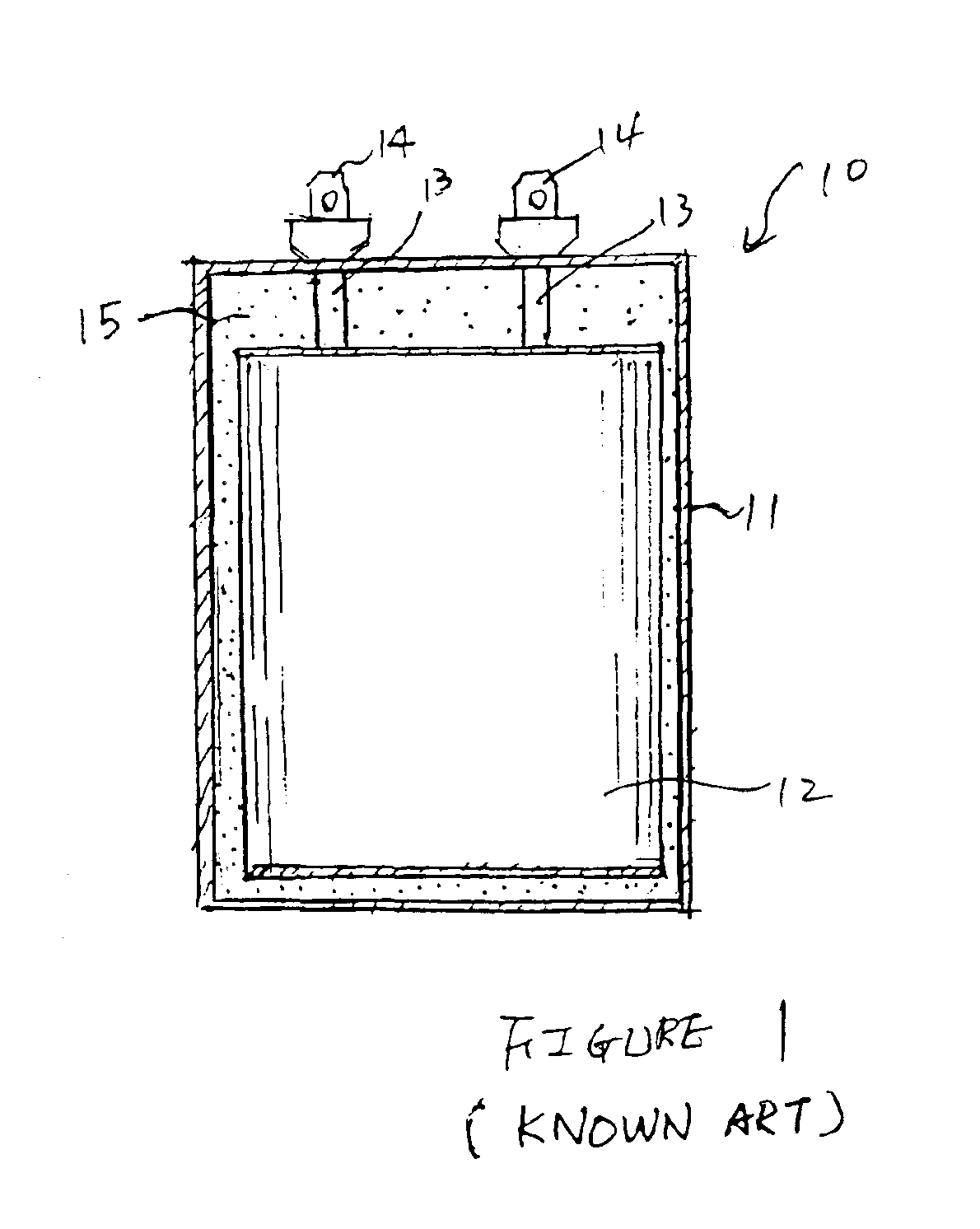
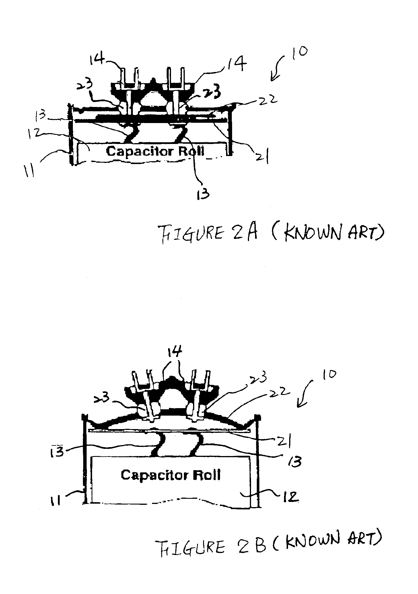
The capacitor shown in FIGS. 2A and 2B, however, is not suitable for providing greater than 15 amps RMS continuous duty.
However, the capacitor is much more costly than any of the other designs mentioned above.
Furthermore, all of the capacitors described above includes an internal interrupter located within the metal housing, which in itself is a significant manufacturing cost.

Method used


Image

  • High current capacitors
  • High current capacitors
  • High current capacitors

Examples


Embodiment Construction

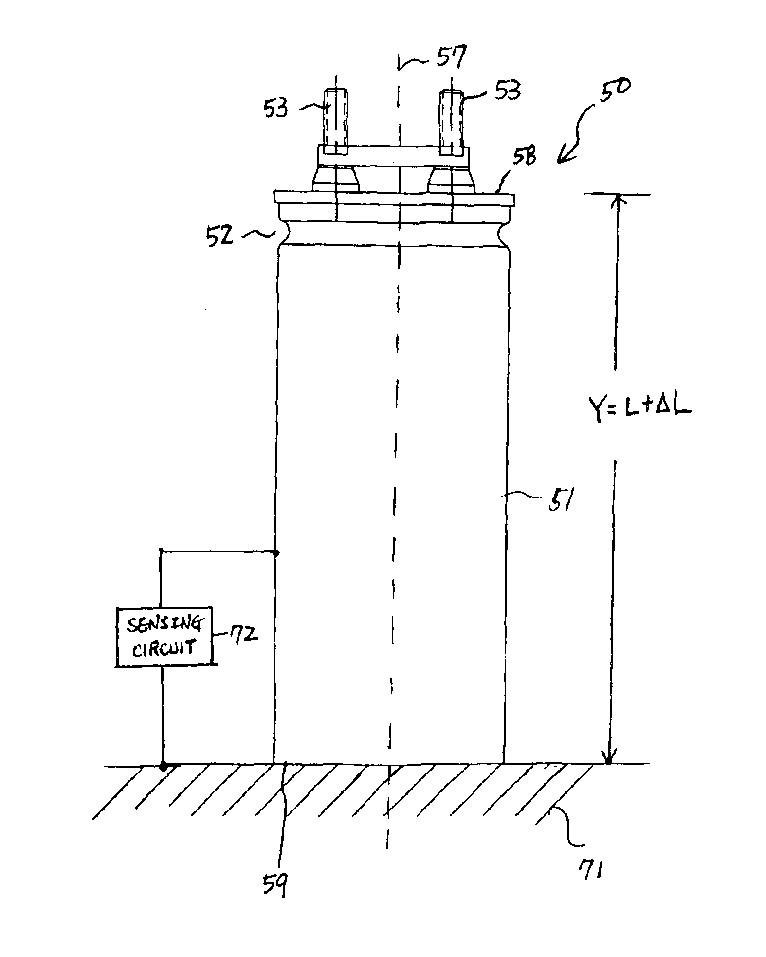
[0036]In one aspect, the present invention provides a capacitor that is configured to trigger an external interrupter. The use of the external interrupter overcomes the disadvantages of the conventional capacitor having an internal interrupter, which typically involves a weak connection in the conductor that can be unnecessarily broken. Using the external interrupter, a capacitor of the present invention can be designed for heavy currents up to or exceeding 50 amps RMS.

[0037]A preferred embodiment of the present invention includes an expandable part in a capacitor housing. The expandable part can be fabricated to resemble a bellows. There is no internal pressure interrupter within the housing of the capacitor. When a fault occurs within the capacitor, the housing increases in length. The increased length of the housing is utilized to make contact with an external circuit. The completion of the external circuit then signals an electrical breaker or contractor to disconnect the capaci...


PUM


Abstract

A capacitor including an expandable part fabricated on a capacitor housing is enclosed. The expandable part is expandable by a fault that occurs within the capacitor housing, thereby extending the capacitor housing to contact with an external interrupter. The external interrupter includes an external electrode and an external sensing circuit. The external sensing circuit detects a contact between the capacitor housing and the external electrode and sends a signal to disconnect the capacitor from an apparatus circuit.

Description

[0001]This application is a continuation of U.S. patent application Ser. No. 10 / 392,847, filed Mar. 21, 2003 U.S. Pat. No. 6,819,545, which is herein incorporated by reference in its entirety.BACKGROUND[0002]1. Field of the Invention[0003]The present invention generally relates to capacitors and, more particularly, to high current capacitors.[0004]2. Background of the Invention[0005]Capacitors are widely used in electrical apparatus for different reasons. For example, capacitors can be used to store electrical charge and to generate a large electrical current and voltage, and the like.[0006]Capacitors can be manufactured using different methods. More recently, capacitors, such as a metallized film capacitors, can be manufactured by wrapping two tightly wound sheets or sections around a core. Each sheet is composed of a dielectric film having a metallized layer disposed on one face of the film. The metallized layer extends to one edge of the face to provide an unmetallized edge. The ...

Claims


Application Information

Patent Timeline
Patent Type & Authority Patents(United States)
IPC IPC(8): H01G2/00H01G4/00H01G9/00H01G9/12
CPCH01G9/12
Inventor LOBO, EDWARD M.MELLO, FRANCIS
Owner PARALLAX POWER COMPONENTS
Why Eureka
Try Eureka