Parallel fiber-fan-out optical interconnect for fiber optic system
a fiber optic system and fiberfanout technology, applied in the direction of fiber mechanical structures, bundled fibre light guides, instruments, etc., can solve the problems of reducing yield, time-consuming and expensive individual handling of fibers, and osa to be discarded
- Summary
- Abstract
- Description
- Claims
- Application Information
AI Technical Summary
Benefits of technology
Problems solved by technology
Method used
Image
Examples
first embodiment
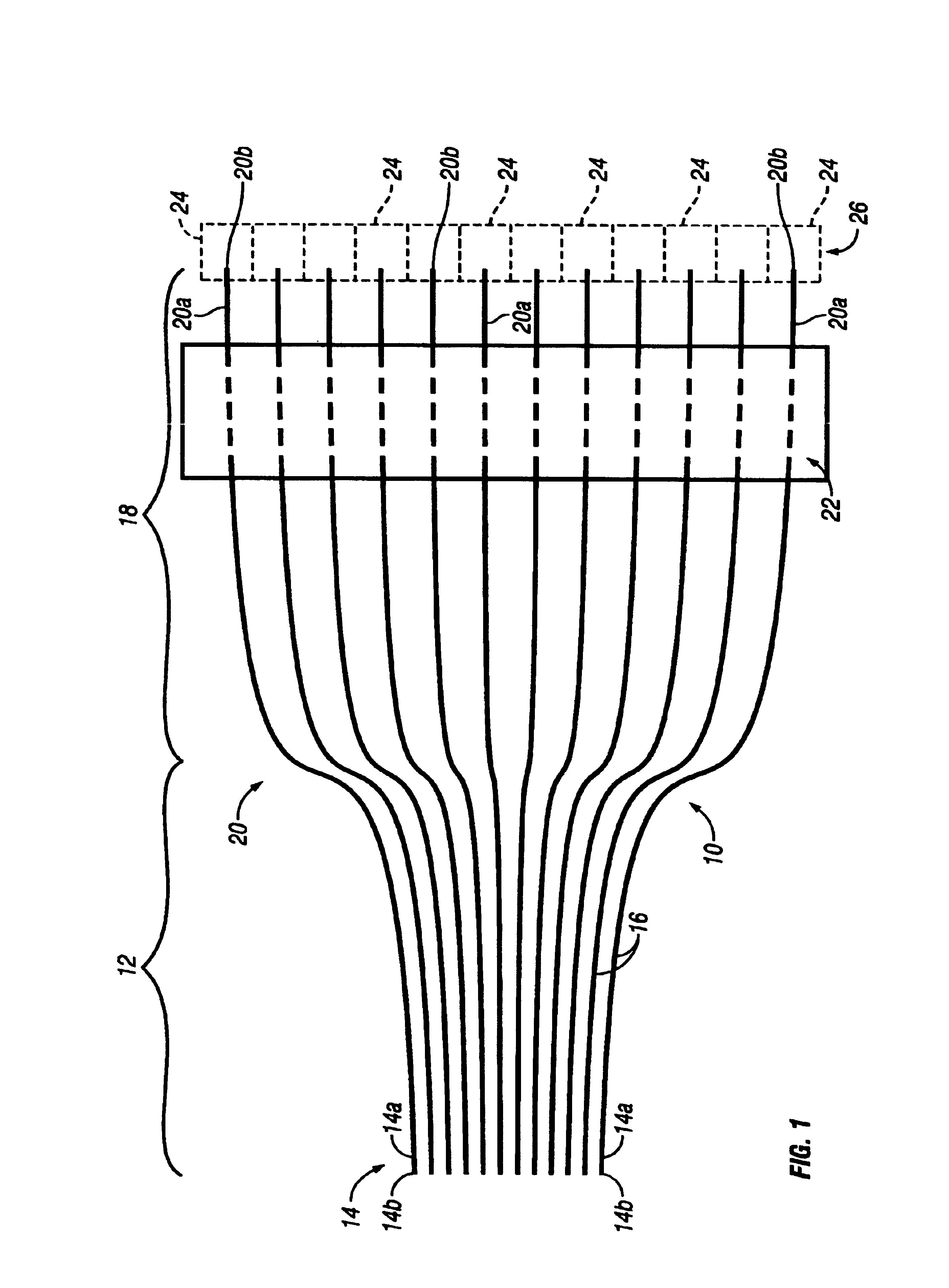
[0014]Referring to FIG. 1, a parallel fiber-fan-out (FFO) optical interconnect 10 in accordance with the present invention has a fiber ribbon 12 including a plurality of first segments 14 of optical fibers 16 extending longitudinally in a planar side-by-side arrangement having a first predetermined pitch, such as two-hundred and fifty micro-meters. The optical fibers 16 could be either plastic optical fiber (POF) or glass optical fiber (GOF). Clearly the center-to-center spacing or pitch is much greater where the optical interconnect is designed for POF than where it is designed for GOF. A fiber-fan-out 18 including a plurality of second segments 20 of the optical fibers 16 extends in a diverging arrangement from the fiber ribbon 12. The first segment 14 and the second segment 20 of each optical fiber 16 are sections or lengths of the same continuous uninterrupted optical fiber. A generally rectangular fiber holder 22 made of molded plastic extends transversely across the plurality ...
second embodiment
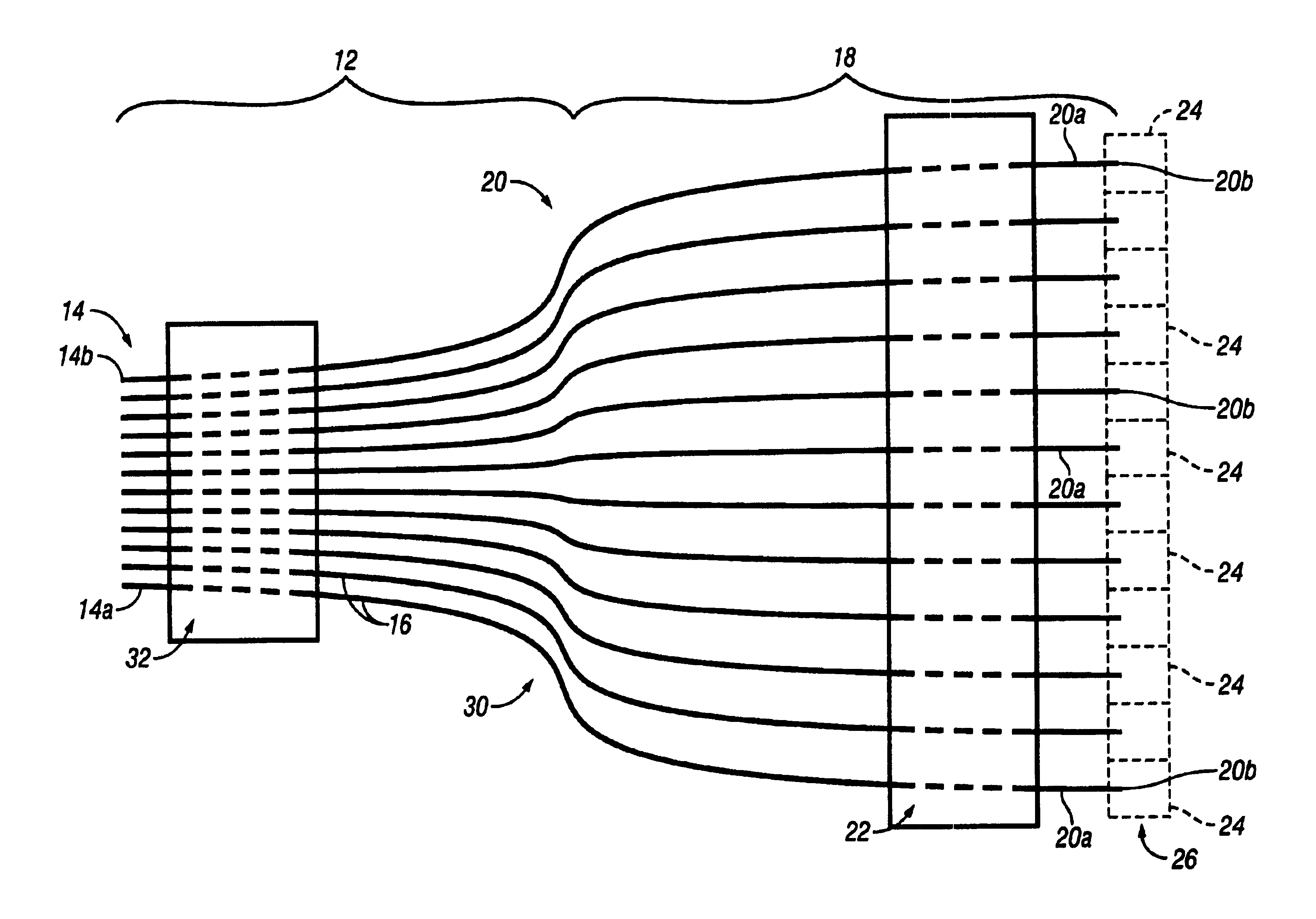
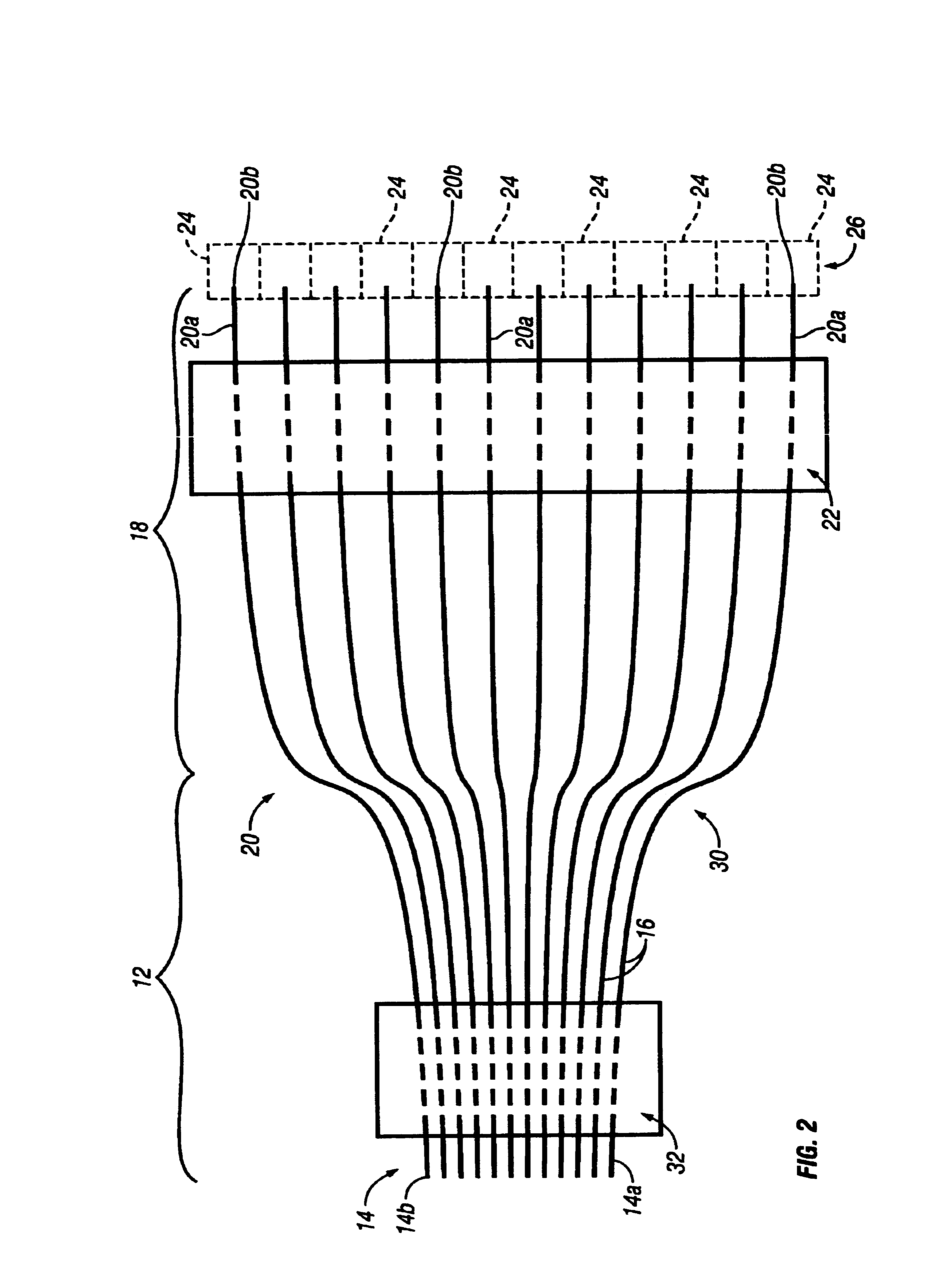
[0019]FIG. 2 illustrates a parallel fiber-fan-out optical interconnect 30 in accordance with the present invention. The optical interconnect 30 is similar to the optical interconnect 10 except that the former has a second generally rectangular fiber holder 32. The fiber holder 32 is a separate discrete body member that maintains the terminal portions 14a of the first segments 14 of the optical fibers 16 in the first predetermined pitch instead of the ribbonizing or web material of the fiber ribbon 12 which is not part of the optical interconnect 30. In FIG. 2, the intermediate portions of the first segments 14 of the optical fibers 16 that pass through the second fiber holder 32 are shown in broken lines to indicate that they are concealed. The second fiber holder 32 can be formed in any of the fashions described above in connection with the first fiber holder 22, i.e. with the optical fibers 16 either being inserted through pre-formed holes, clamped around, molded over, and optiona...
third embodiment
[0020]FIG. 3 illustrates a parallel fiber-fan-out optical interconnect 40 in accordance with the present invention. A common injection molded plastic housing assembly 42 illustrated in phantom lines surrounds the first segments 14 and the second segments 20 of the optical fibers 16 except for their terminal portions 14a and 20a, respectively. The housing assembly 42 may have flat opposing flat faces with stepped side edges similar to the configuration of multi-pin electrical connectors that are plugged into personal computers. The housing assembly 42 holds the terminal portions 14a in the first predetermined pitch and the terminal portions 20a in the second predetermined pitch. Thus the cleaved ends 14b of the first segments 14 can be mated with the corresponding ends of the routed optical fibers held in the mating conventional parallel fiber connector (not illustrated). It also allows the cleaved ends 20b of the terminal portions 20a of the second segments 20 to be mated with the O...
PUM
 Abstract
Description
Claims
Application Information
 - R&D
- Intellectual Property
- Life Sciences
- Materials
- Tech Scout
- Unparalleled Data Quality
- Higher Quality Content
- 60% Fewer Hallucinations
Browse by: Latest US Patents, China's latest patents, Technical Efficacy Thesaurus, Application Domain, Technology Topic, Popular Technical Reports.
© 2025 PatSnap. All rights reserved.Legal|Privacy policy|Modern Slavery Act Transparency Statement|Sitemap|About US| Contact US: help@patsnap.com


