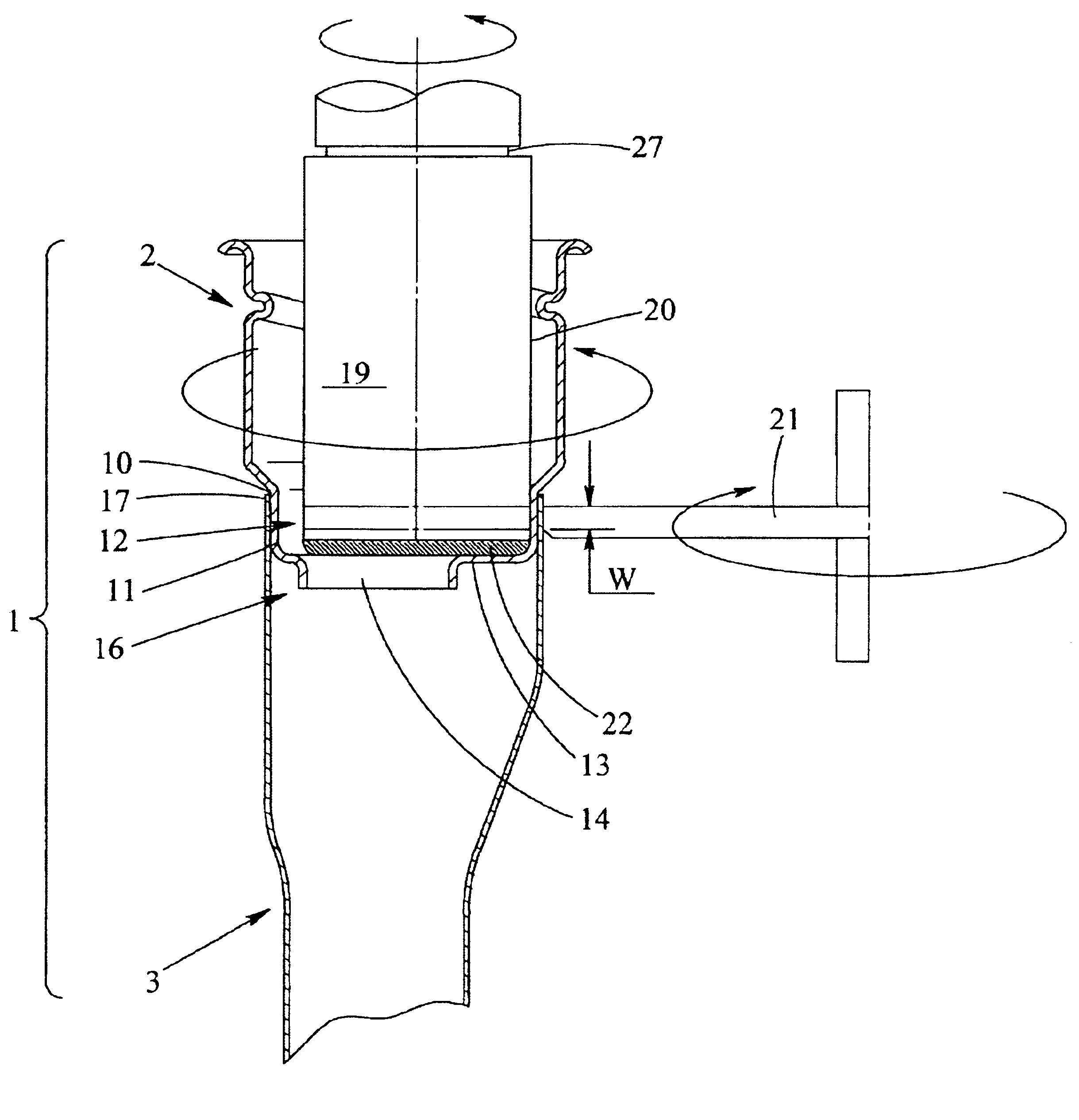
[0011]In the present invention, the circumferential wall portion of the mouthpiece and the circumferential wall portion of the feeding pipe are jointed by
seam welding in a press-fitted condition. Specifically, a welding area W established in a range of a width of the portion overlapping the circumferential wall portions of the mouthpiece and of the feeding pipe is welded apart from the overlapped
peripheral edge of the feeding pipe by
seam welding. As a result, there are no melting drops of the weld at the overlapped
peripheral edge portion of the feeding pipe, and thereby the high hermeticity of the filler neck can be obtained. In addition, there is no scattering of spatters in the seam welding which requires no clearances at the welding area W. At the same time, the seam welding as a high-speed welding operation brings enhancement of productivity of the filler neck. Moreover, the seam welding can also achieve a reliable welding result in
spite of producing tight or loose tolerances, because of that nothing of sub-materials for welding is required, nor that the shapes of the peripheral edges of the mouthpiece and the feeding pipe influences to the result of the joint.
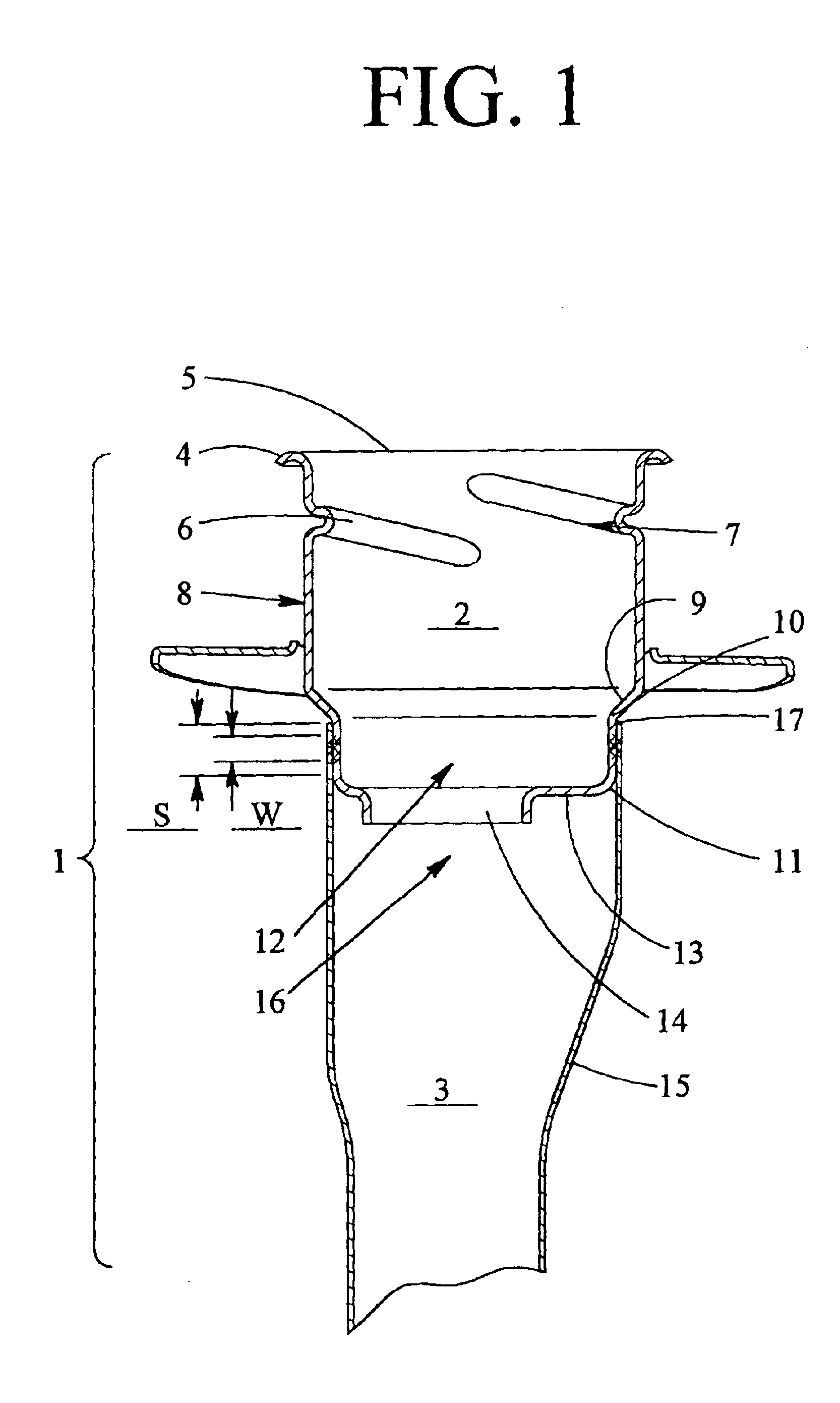
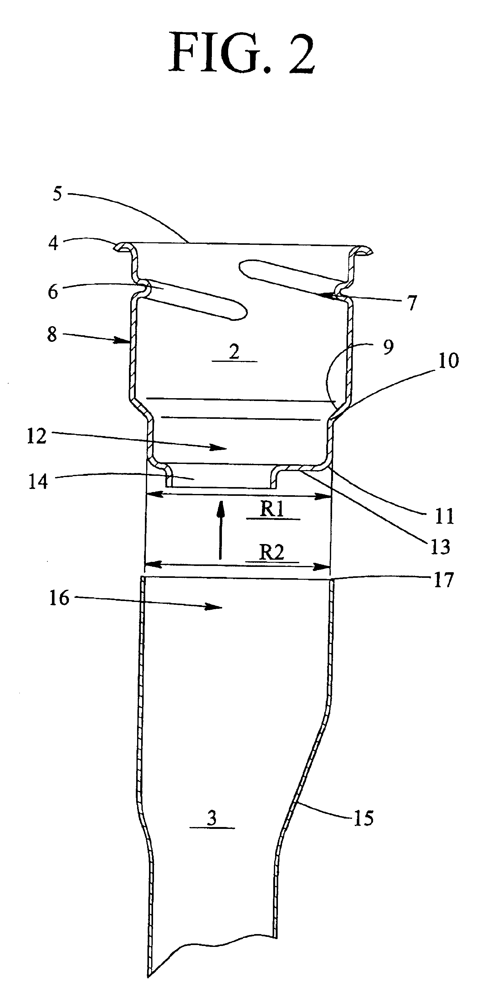
[0012]In order to perform the seam welding under the condition of in which the welding area W is provided to the overlapped area S defined by press-fitting the circumferential wall portion of the feeding pipe over the circumferential wall portion of the mouthpiece, the circumferential wall portion of the mouthpiece is formed into a cylinder extending downwardly toward the feeding pipe, and the circumferential wall portion of the feeding pipe is formed into a cylinder having a shape substantially equal to the outer cross-sectional shape of the circumferential wall portion of the mouthpiece. Thereby, the circumferential wall portion of the feeding pipe can be fitted over the circumferential wall portion of the mouthpiece in a press-fitted condition free from occurrence of clearance therebetween. In general, the shape of the body of the mouthpiece excepting of the circumferential wall portion and the shape of the body of the feeding pipe excepting of the circumferential wall portion are in a sectional circular shape. Therefore, the circumferential wall portion of the mouthpiece is formed by reducing diameter of the body of the mouthpiece. At the same time, the circumferential wall portion of the feeding pipe is formed by enlarging diameter of the body of the feeding pipe. Since the circumferential wall portions of the mouthpiece and the feeding pipe are in an overlapped relation with each other, formation of each wall portion into a cylinder in a sectional circular shape provides flexibility in orientation of the mouthpiece relative to the feeding pipe and capability of
assembly of both the circumferential wall portions at a
fixed position. In addition to the above advantages, there is no deviation in strength between each circumferential wall portion as being of a cylinder in a sectional circular shape.
[0013]A fitting volume of the circumferential wall portion of the feeding pipe over the circumferential wall portion of the mouthpiece controls the region width of the overlapping area S between the circumferential wall portions of the mouthpiece and the feeding pipe in a press-fitted condition. Setting an extent of the fitting volume of the circumferential wall portions or the region width of the overlapping area S can be flexible, so long as the width of the seam welding area W stays within the overlapping area S. However, the greater the fitting volume of the circumferential wall portions of the mouthpiece and the feeding pipe becomes, the harder the press-fitting becomes. Additionally, it is not preferable, from the viewpoint of uniformity of the product's quality, that the fitting volume varies in every products. Accordingly, the circumferential wall portion of the mouthpiece may be formed by reducing in diameter of the body of the mouthpiece through a tapered portion into a sectional circular shape, an upper end of the circumferential wall portion of the mouthpiece may be defined by a boundary portion between the tapered portion and the circumferential wall portion of the mouthpiece, and thereby the circumferential wall portion of the mouthpiece may be fitted in the circumferential wall portion of the feeding pipe in a manner that the peripheral edge of the feeding pipe abuts to the upper end of the circumferential wall portion of the mouthpiece. To press-fit the circumferential wall portions in the aforementioned manner can usually set the overlapping area S in a fixed range. This means that the mouthpiece and the feeding pipe can be positioned easily at the step of the assembling prior to the welding step. Moreover, a constant seam-welding area W can be provided in a range of the overlapped area S of the circumferential wall portions of the mouthpiece and the feeding pipe. As a result, uniformity of the product's quality can be achieved.
[0014]A partition of the mouthpiece may be formed by radially and inwardly reducing a lower edge of the circumferential wall portion of the mouthpiece having a sectional circular shape as an orthogonal surface to the circumferential wall portion of the mouthpiece. An annular rib functioning as a gun guide may be formed to be downwardly projected from the partition. The internal welding
electrode may be rotated while sliding an insulated
nose face thereof contacting onto an inner face of the partition of the mouthpiece. A rigidity of the circumferential wall portion of the mouthpiece is enhanced by presence of the partition. A rigidity of the partition is also enhanced by presence of the annular rib. Accordingly, the shape of the circumferential wall portion of the mouthpiece can be retained by the enhanced rigidity at the step of press-fitting the circumferential wall portion of the mouthpiece in the circumferential wall portion of the feeding pipe. The annular rib functioning as a gun guide may be formed in a conical shape by gradually and successively reducing the circumferential wall portion of the mouthpiece. It is more preferable that the annular rib is integrally formed by folding the circumferential wall portion of the mouthpiece in order that the partition formed by folding the circumferential wall portion orthogonally and radially is folded vertically downward. Thus, the rotating position of the internal welding
electrode during seam-welding becomes stable by the effect of the partition which supports a
nose face of the internal welding
electrode in
sliding contact, resulting in an optimized seam welding. Since the annular rib as a gun guide extending from the partition is arranged apart from the circumferential wall portion of the mouthpiece, the circumferential wall portion of the mouthpiece can be prevented from suffering damages occurred by a filler gun's
insertion. Furthermore, the annular rib of the present invention is applicable to manufacture the various types of products with a common structure in a same
production line; in accordance with difference of the fuel classifications, alteration of the gun guide's diameter adjusting to the individual
national standard of the device, and alteration of the structure of the filler neck depending upon the individual legal requirements.

