
Apparatus and method for determining a liquid level in a steam drum

a technology of liquid level and apparatus, which is applied in the direction of lighting and heating apparatus, instruments, machines/engines, etc., can solve the problems of insufficient solution, rife with errors in the remote level indication method, and inability to provide the desired measurement accuracy, etc., to achieve accurate reading of liquid level

Active Publication Date: 2005-08-23
VOGT POWER INT
View PDF19 Cites 24 Cited by
  • Summary
  • Abstract
  • Description
  • Claims
  • Application Information

AI Technical Summary

Benefits of technology

[0008]The present invention is an apparatus and method for determining liquid level in a steam drum or similar vessel, and, more particularly, an apparatus and method that allows for a more accurate reading of the liquid level in a steam drum or similar vessel by compensating for operating pressures and temperatures, which are often subject to rapid and continuous variations.

Problems solved by technology

Using a water column and conductivity probes, however, does not always provide the desired measurement accuracy.
Indeed, it is common that the water column and conductivity probe arrangement provides measurements that are in disagreement with the computerized master control system, since the probe method is only accurate for one set of operating conditions.
However, such a method of remote level indication is rife with error as a standard water column with conductivity probes is only accurate at a single predefined set of operating conditions.
However, since an appropriate adjustment would be required each time the operating conditions are altered, such a solution has not proved satisfactory.

Method used


Image

  • Apparatus and method for determining a liquid level in a steam drum
  • Apparatus and method for determining a liquid level in a steam drum
  • Apparatus and method for determining a liquid level in a steam drum

Examples


Embodiment Construction

[0014]The present invention is an apparatus and method for determining liquid level in a steam drum or similar vessel (especially any vessel operating at or near saturated conditions), and, more particularly, an apparatus and method that allows for a more accurate reading of the liquid level in a steam drum or similar vessel by compensating for operating pressures and temperatures, which are often subject to rapid and continuous variations.

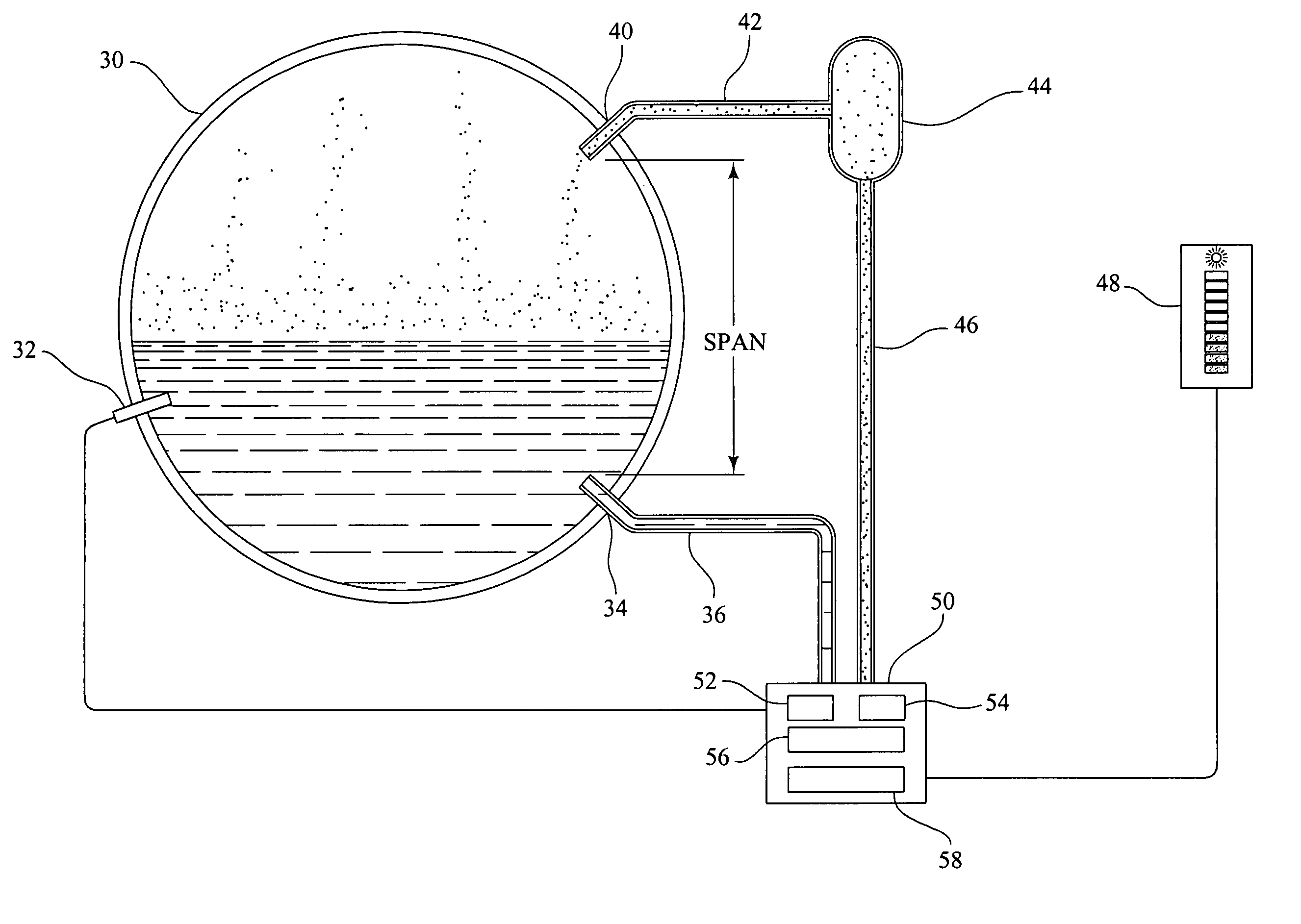
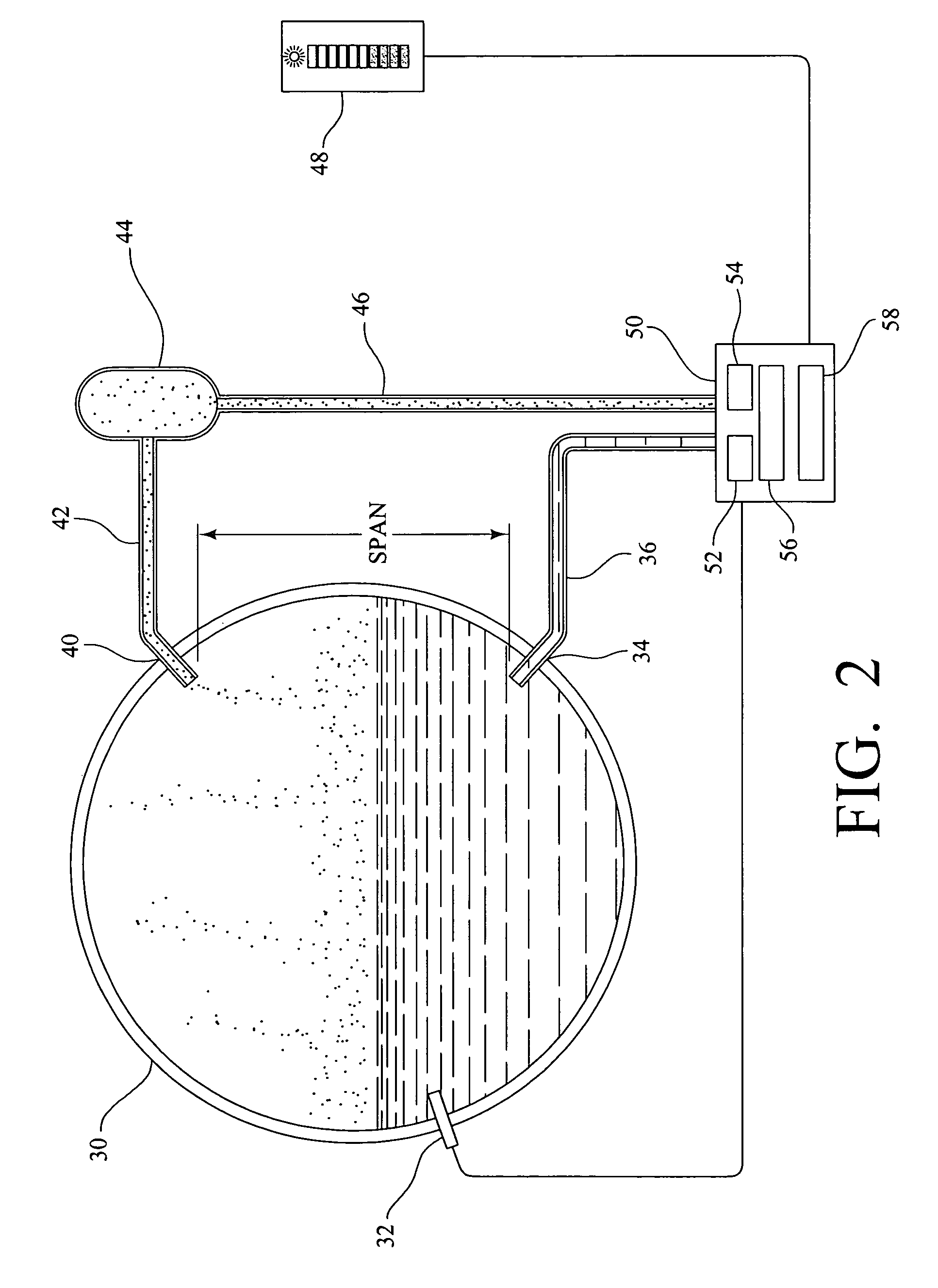
[0015]Referring now to FIG. 2, a steam drum 30 contains a mixture of liquid and vapor. As stated above, the objective is to obtain an accurate reading of the liquid level in the steam drum 30. Accordingly, the drum 30 is provided with a temperature sensor 32 which produces an electrical signal that is proportional to the temperature of the mixture, transmitting that signal to a processing apparatus 50, which is referred to as a “multi-variable transmitter” in the description that follows and the function of which is further explained below. Then, ...


PUM


Abstract

An apparatus for determining a density-compensated liquid level in a vessel containing a mixture of liquid and vapors comprises a temperature sensor which produces a signal that is proportional to the temperature of the mixture; and a processing apparatus that includes one or more pressure sensors that allow for a measurement of an operating pressure and a differential pressure between the mixture in the vessel and a constant reference leg. The processing apparatus further includes an integral microprocessor for calculating the respective specific gravities of the liquid and vapor portions of the mixture based on the operating pressure, and then computing the density-compensated liquid level in the vessel based on such calculations of specific gravity and the differential pressure.

Description

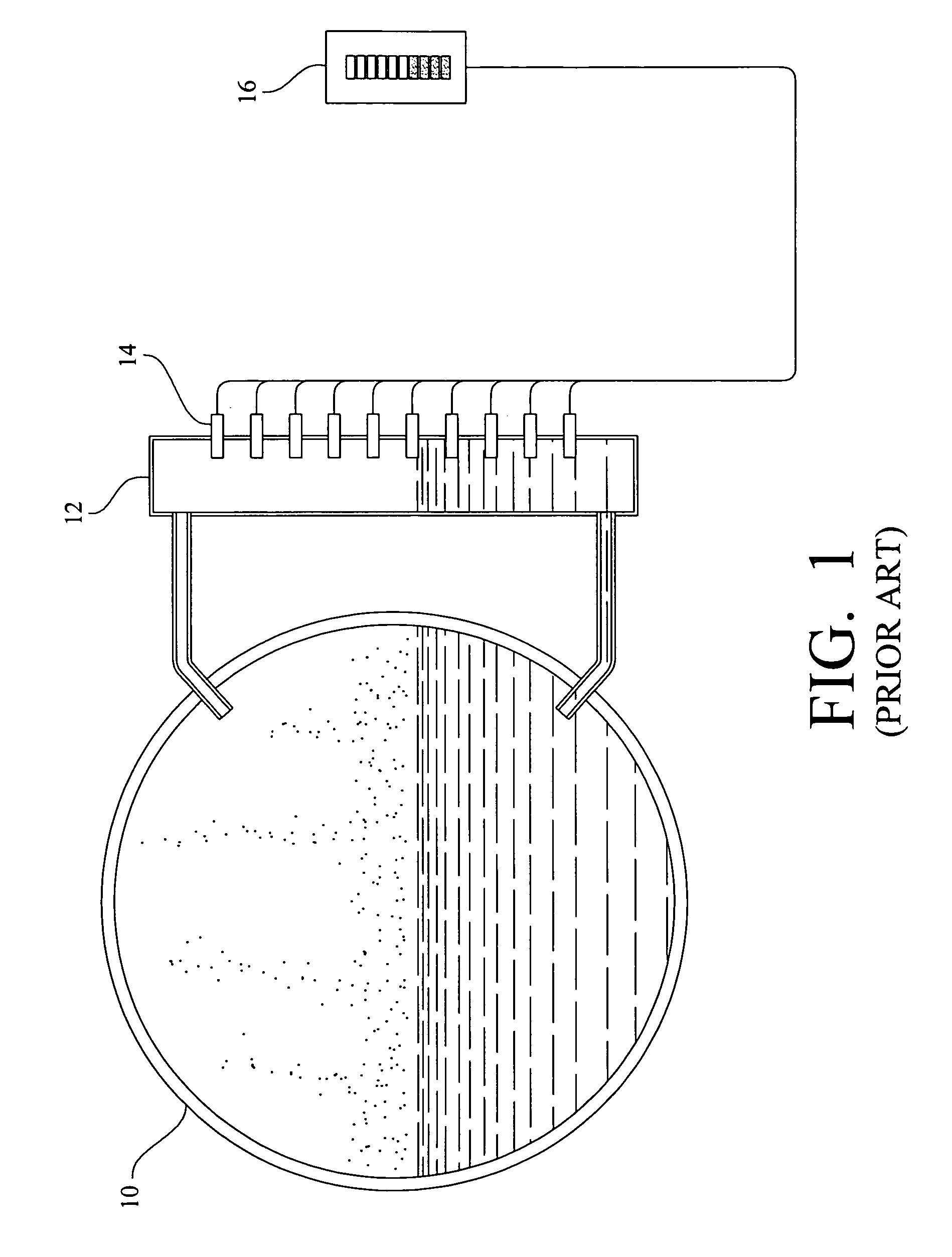
BACKGROUND OF THE INVENTION[0001]The present invention relates to an apparatus and method for determining liquid level in a steam drum or similar vessel operating at or near saturated conditions, and, more particularly, an apparatus and method that allows for a more accurate reading of the liquid level in a steam drum or similar vessel by compensating for variances in operating pressures and temperatures.[0002]The American Society of Mechanical Engineers (“ASME”) has promulgated a Boiler Code, which, in pertinent part, states that “[a]t least one gage glass shall be readily visible to the operator in the area where control actions are initiated. Alternately, two dependable indirect indications shall be provided, either by transmission of the gage glass image or by remote level indicators . . . ” ASME Boiler Code, Section I, Part PG-60.1.1.[0003]Since it is often difficult to have a gage glass in the immediate vicinity of the control room, the alternate option is typically preferred,...

Claims


Application Information

Patent Timeline
Patent Type & Authority Patents(United States)
IPC IPC(8): F22B37/00F22B37/46G01F23/14F22B37/78G01F23/02G01F23/18G01F23/24
CPCF22B37/78G01F23/02G01F23/18G01F23/243
Inventor HATFIELD, PAULKEARNEY, HAROLD
Owner VOGT POWER INT
Learn More