Connector incorporating a contact pad surface on a plane parallel to a longitudinal axis

a contact pad and surface technology, applied in the direction of coupling device connection, instrument, therapy, etc., can solve the problems of limited design life relative to the life of the energy generator, the designer of the connector, and the prior art connector for the energy-transfer system that has not adequately fulfilled users' needs

Inactive Publication Date: 2005-08-23
ETHICON ENDO SURGERY INC
View PDF27 Cites 127 Cited by
  • Summary
  • Abstract
  • Description
  • Claims
  • Application Information

AI Technical Summary

Benefits of technology

[0009]An improved connector for attaching a usage-limited delivery device to an energy generator comprises at least one electrical contact pad having a contact surface located on a plane parallel to the axis of rotation of the connector and positioned so that rotation of the connector engages the contact pad to a conductive contact on the energy generator in a direction substantially perpendicular to the contact pad. An embodiment of the connector places several contact pads within a flange radially extending from the longitudinal axis of the connector. The flange can also have an associated memory device and can contain the memory device and contact pads as a printed circuit board assembly insert-molded into the flange. The connector is rotatable from an unlocked position having the contact pads disengaged from the conductive contacts to a locked position having the contact pads engaged with the conductive contacts. When the connector is rotated into the locked position, a wall on a connector housing obstructs proximal movement of the flange on the connector to prevent removal of the connector from the housing.

Problems solved by technology

The energy delivery device is usually inexpensive relative to the energy generator and has a limited design life relative to the life of the energy generator.
Locating the necessary electrical signal contacts within one connector presents problems for a designer of the connector.
Prior art connectors for energy-transfer systems have not adequately fulfilled users' needs.
Connectors that attach with a straight push and no rotation may give unsatisfactory tactile feedback to the user of an adequate connection.
Connectors attaching with rotation to energy generators may have electrical contacts that use sliding contact when the connector is rotated, limiting design life of the contacts on the energy generator through friction and wear.

Method used


Image

  • Connector incorporating a contact pad surface on a plane parallel to a longitudinal axis
  • Connector incorporating a contact pad surface on a plane parallel to a longitudinal axis
  • Connector incorporating a contact pad surface on a plane parallel to a longitudinal axis

Examples


Embodiment Construction

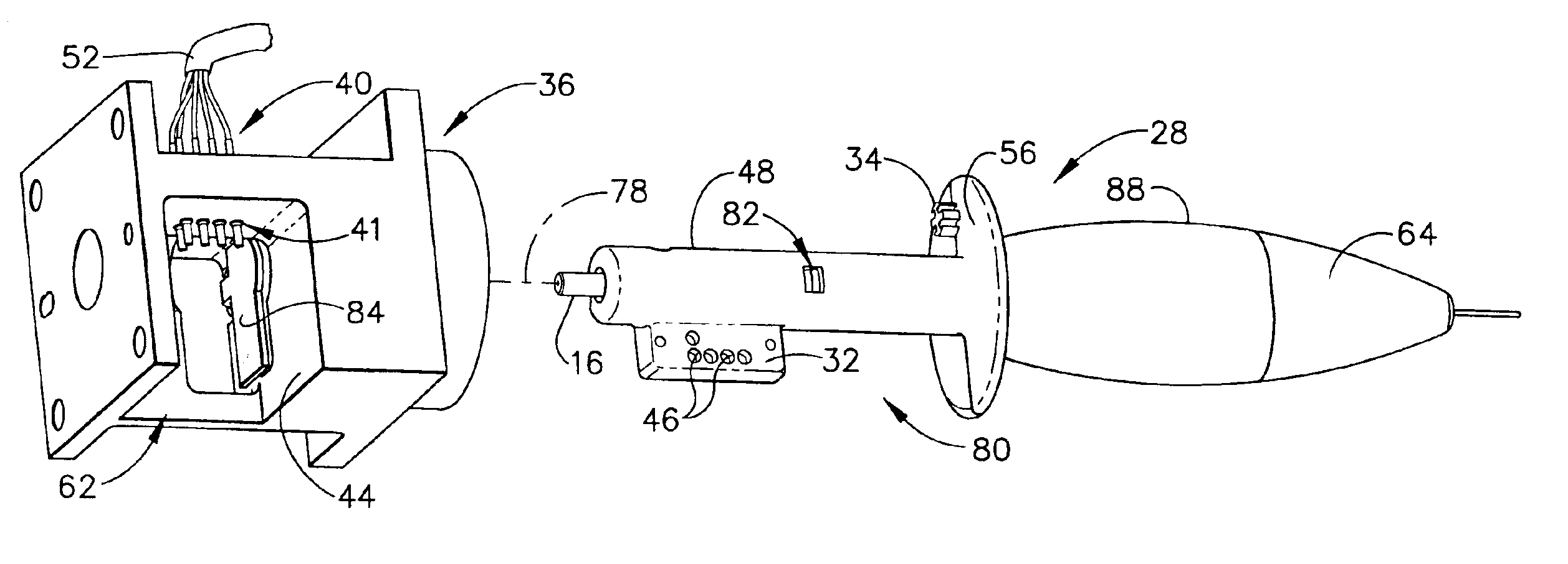
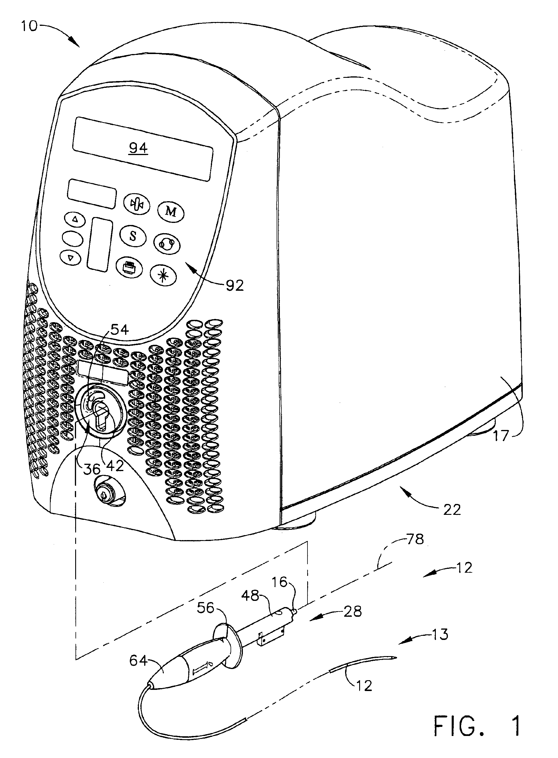
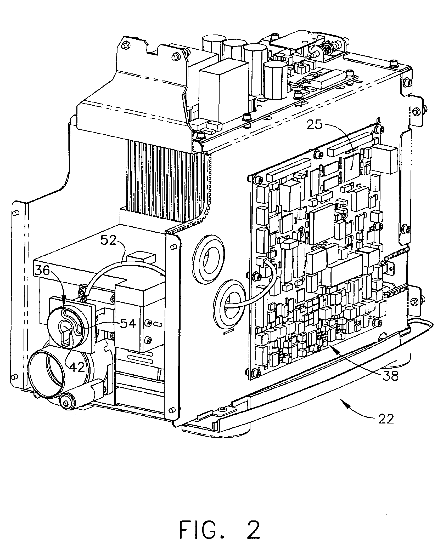
[0027]FIG. 1 shows a system 10 for transferring diffused light to human tissue incorporating a connector according to an embodiment of the present invention. A laser 22 is provided with system 10 to generate energy in the form of laser light. A cover 17 shields interior components of laser 22, and a connector housing 36 resides within a front portion of cover 17. The front of connector housing 36 is exposed to the exterior. System 10 further includes an optical fiber assembly 12 having connector 28 at its proximal end. Optical fiber assembly 12 is attachable to connector housing 36 by inserting connector 28 through an opening 42 in connector housing 36. An optical fiber 13 extends proximally from connector 28. Optical fiber 13 may be, for example, a standard optical fiber possessing a light transmitting core, cladding, and a jacket. Optical fiber 13 may have a diffuser tip located at the end opposite connector 28. The diffuser tip may be used to diffuse light for medical treatment o...


PUM


Abstract

An improved connector capable of transferring both energy and electrical signals between an energy generator and an energy transfer device is disclosed. The connector attaches the energy transfer device to the energy generator by rotation about a longitudinal axis. The connector carries at least one contact pad that has a surface on a plane parallel to the longitudinal axis. A line passing through the surface of the contact pad perpendicular to the plane is skew to the longitudinal axis, so that rotation of the connector engages the contact pad with conductive contacts associated with the energy generator in a direction substantially perpendicular to the contact pad.

Description

[0001]This application claims the benefit of U.S. Provisional Application No. 60 / 243,669, filed Oct. 27, 2000.FIELD OF THE INVENTION[0002]The present invention relates, in general, to an improved connector to transfer energy from an energy generator and an energy transfer device and electrical signals between at least one conductive contact on the energy generator and at least one contact pad on the energy delivery device, and more particularly, to an improved connector rotatably attachable to an energy generator wherein the rotation of the connector about a longitudinal axis engages the electrical contact pad with the conductive contact in a direction substantially perpendicular to the contact surface of the contact pad.BACKGROUND OF THE INVENTION[0003]Systems to transfer energy to tissue have been used in the medical field for therapeutic treatment of tissue. These systems generally comprise an energy generator and an energy delivery device. The energy delivery device attaches to ...

Claims


Application Information

Patent Timeline
Patent Type & Authority Patents(United States)
IPC IPC(8): G02B6/38H01R13/71H01R13/70A61B18/20A61B18/00A61B18/22A61B17/00A61N5/06G02B6/42H01R13/639G02B6/36A61B18/12A61B18/18
CPCG02B6/3869G02B6/3891G02B6/3895H01R13/71A61B18/22A61B2017/00477A61B2018/00988A61N5/0601G02B6/3821G02B6/3887G02B6/4296H01R13/6397
Inventor SWAYZE, JEFFREY S.JAMES, BENJAMIN F.
Owner ETHICON ENDO SURGERY INC
Why Eureka
Try Eureka