
Cutting insert for drills having chip-embossing formations for stiffening chips

a technology of cutting inserts and drills, which is applied in the direction of cutting inserts, portable drilling machines, manufacturing tools, etc., can solve problems such as chip breakage, and achieve the effects of reducing chip softness, improving cooling/lubrication, and improving cutting inserts

Active Publication Date: 2005-08-23
SANDVIK INTELLECTUAL PROPERTY AB
View PDF9 Cites 6 Cited by
  • Summary
  • Abstract
  • Description
  • Claims
  • Application Information

AI Technical Summary

Benefits of technology

The embossed surface design accelerates chip breakage and ensures effective cooling at the cutting edge, reducing the risk of chip jamming and improving chip evacuation efficiency.

Problems solved by technology

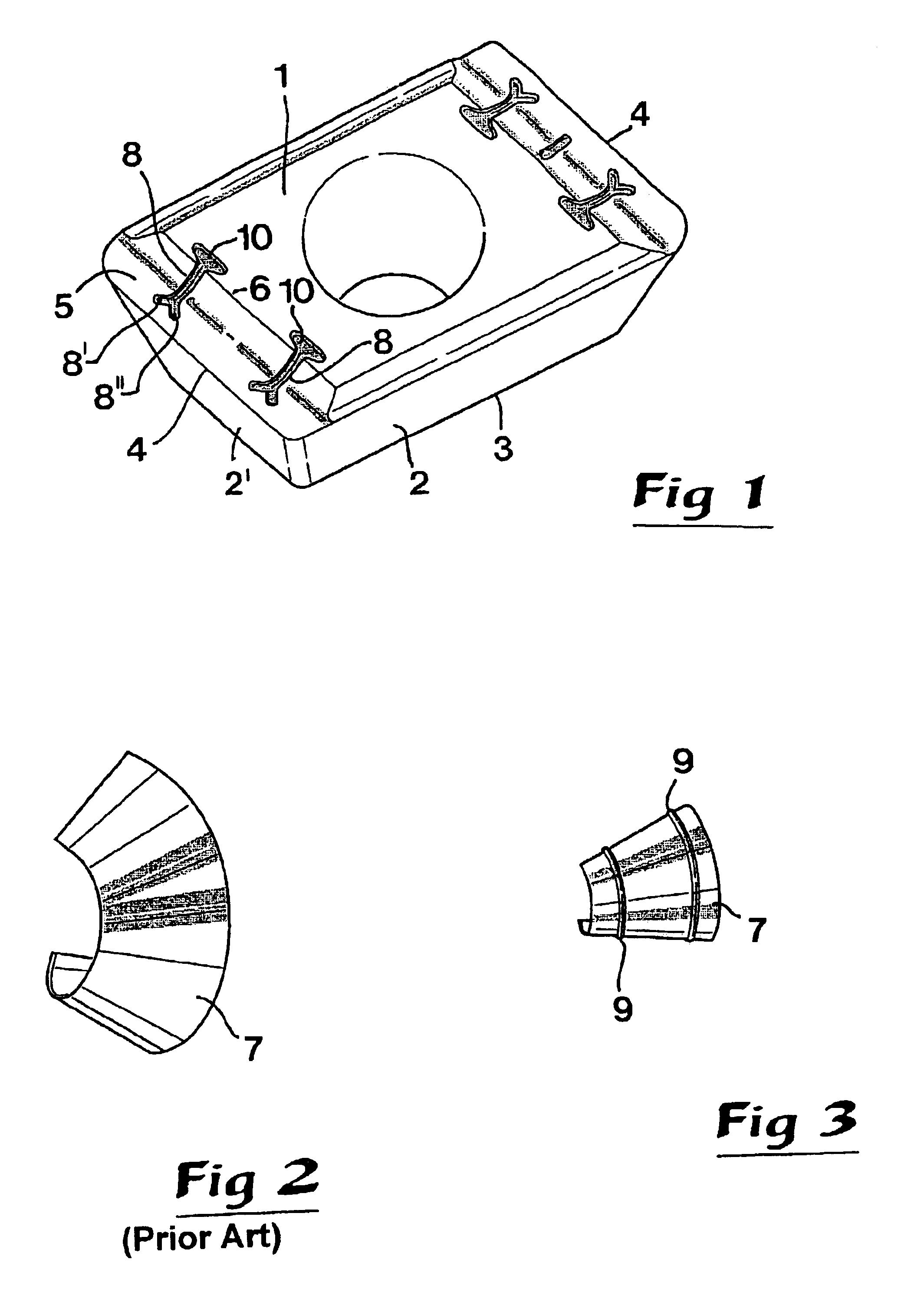
More precisely, tests, which have been performed, have shown that the chip is stiffened by the embossments and in this way, fracture-initiating units are created more rapidly in the chips, which result in chip breakage.

Method used


Image

  • Cutting insert for drills having chip-embossing formations for stiffening chips
  • Cutting insert for drills having chip-embossing formations for stiffening chips
  • Cutting insert for drills having chip-embossing formations for stiffening chips

Examples


Embodiment Construction

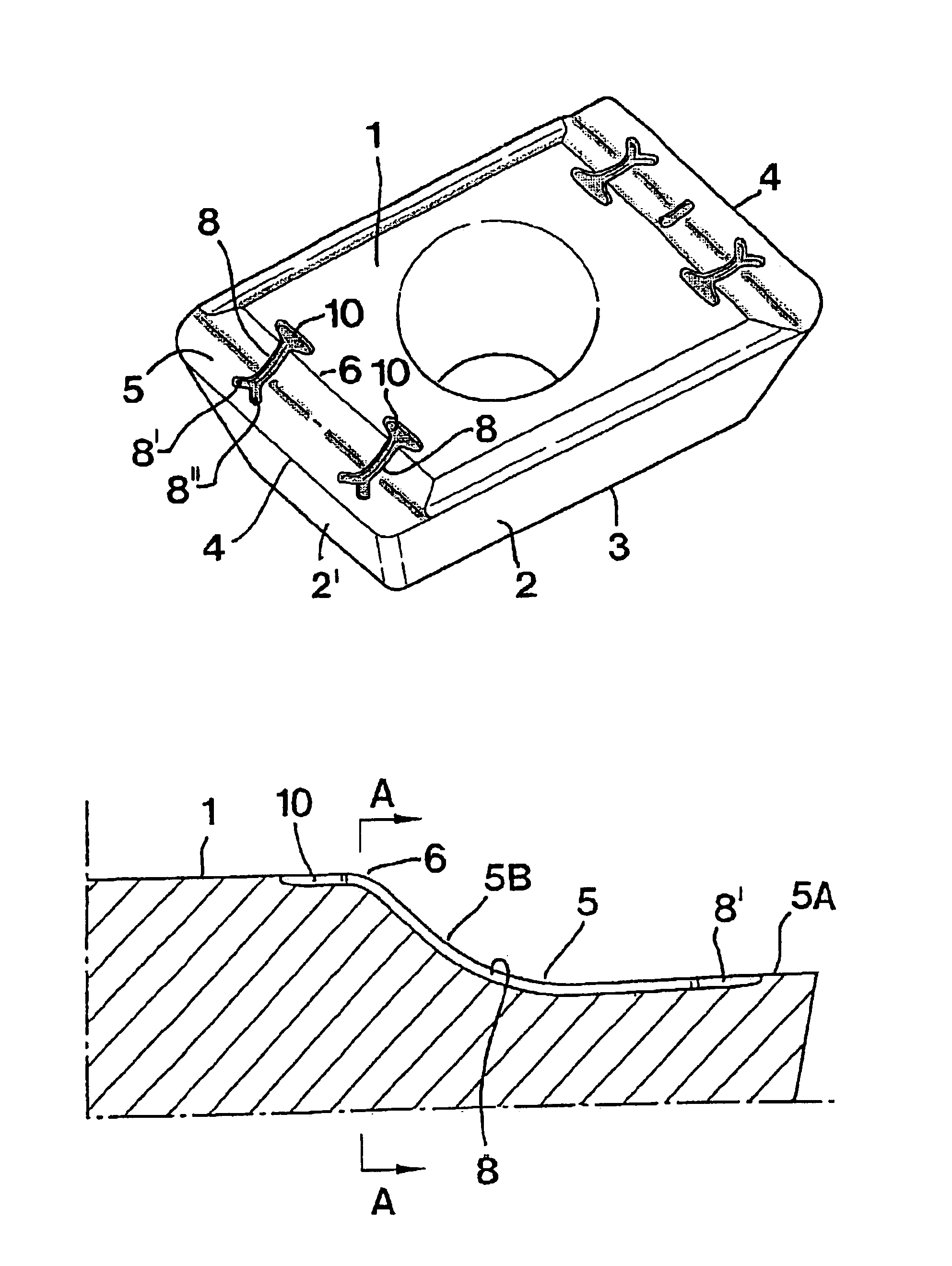
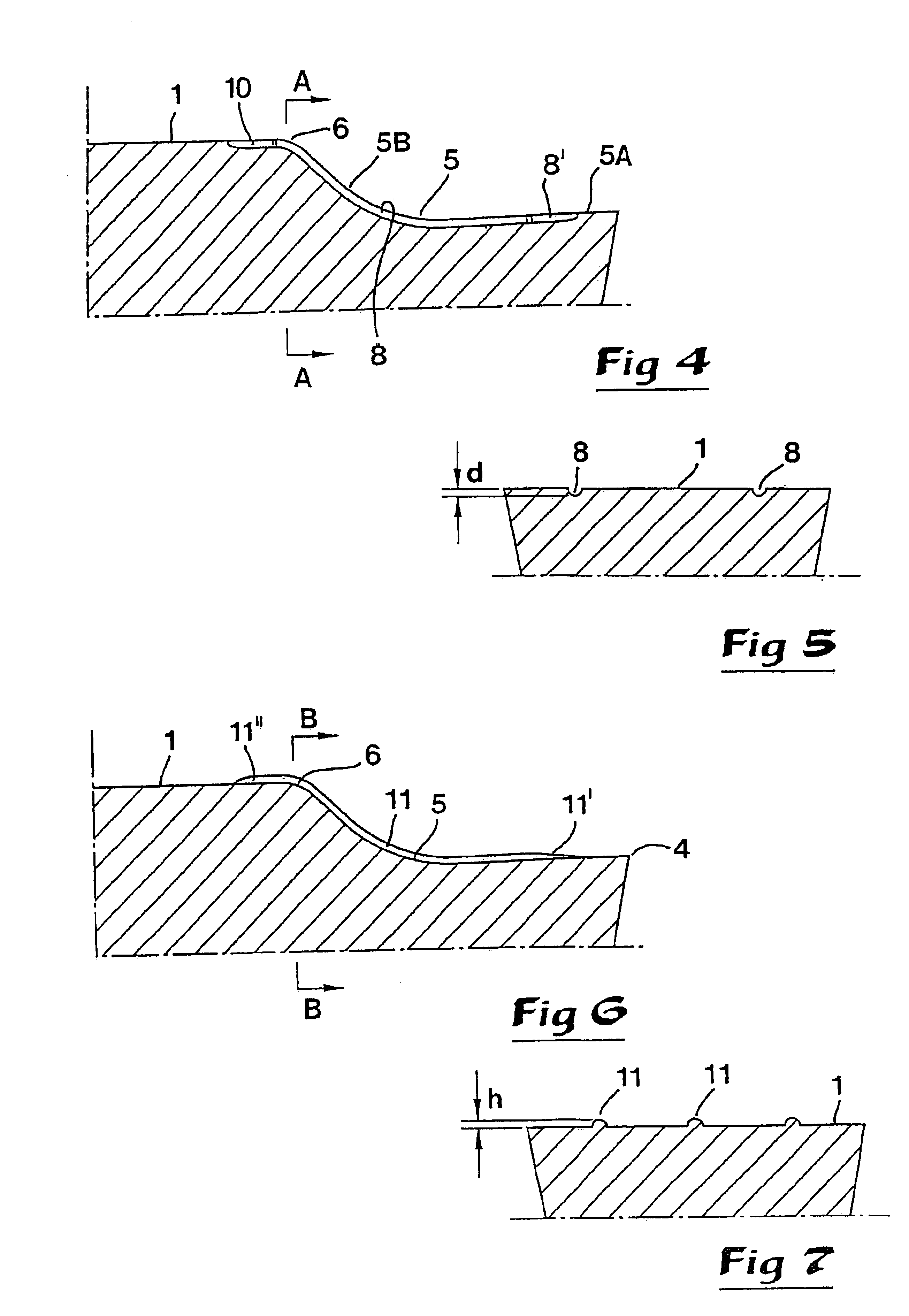
[0015]In FIG. 1, a cutting insert intended for drills, in particular long hole drills, is shown, which in the usual way has a topside 1, a circumferential side surface 2 and a bottom side 3. In the illustrated example, the cutting insert includes two cutting edges 4, each of which is formed individually in connection with a clearance surface 2′ that constitutes a portion of the circumfering side surface 2. From the individual cutting edge 4, a chip removing surface 5 extends up to a back edge and forms therewith a ridge 6, where the chip removing surface transforms into the topside 1 of the cutting insert. As is seen most clearly in FIG. 4, the chip removing surface 5 has a generally concavely curved shape. The actual surface as such is smooth and in the example includes on the one hand an approximately planar surface portion 5A adjacent to the cutting edge 4, and on the other hand a softly rounded surface portion 5B that extends like an inclined slope from the partial surface porti...


PUM

PropertyMeasurementUnit
depthaaaaaaaaaa
depthaaaaaaaaaa
depthaaaaaaaaaa

Abstract

A cutting insert, intended for drills, in particular long hole drills, includes a cutting edge from which a concavely curved, chip removing surface extends up to a ridge where the curved surface transforms into a top side of the cutting insert. A number of long narrow chip-embossing formations (e.g., grooves or beads) extend from the chip removing surface to the top side with the purpose of producing, in the underside of the chip, long narrow embossments in the form of either ridges or flutes in order to stiffen the chip and make it more prone to breakage.

Description

[0001]This application claims priority under 35 U.S.C. §§ 119 and / or 365 to patent application Ser. No. 0201966-9 filed in Sweden on Jun. 26, 2002 the entire content of which is hereby incorporated by reference.BACKGROUND OF THE INVENTION[0002]This invention relates to a cutting insert, intended for drills, of the type that comprises a cutting edge from which a concavely curved, chip removing surface extends up to a ridge, where the curved surface transforms into a top side of the cutting insert. The invention also pertains to a method of chip-forming drilling.[0003]When drilling in workpieces of, for instance, metal, there is a general desire that the chips cut free should be as short as possible in order to be evacuated from the hole being produced in the easiest conceivable way. If the chips become long, like a lock of curly hair, a risk of chip jamming arises. These difficulties become particularly marked in connection with long hole drilling in materials that form long chips, i...

Claims


Application Information

Patent Timeline
Patent Type & Authority Patents(United States)
IPC IPC(8): B23B27/14B23B51/00B23B27/22
CPCB23B27/143B23B2200/081B23B2200/087Y10T407/245Y10T408/566Y10T407/235Y10T407/24B23B51/00
Inventor VANBERG, MATTIAS
Owner SANDVIK INTELLECTUAL PROPERTY AB
Learn More