Disc shaped filter

a filter and disc technology, applied in the field of disc filters, can solve the problems of blocking other vascular regions, affecting the function of the filter, and causing damage to tissue and/or body organs

Inactive Publication Date: 2005-08-23
BOSTON SCI SCIMED INC
View PDF243 Cites 75 Cited by
  • Summary
  • Abstract
  • Description
  • Claims
  • Application Information

AI Technical Summary

Benefits of technology

[0006]The present invention pertains to distal protection filter devices. A distal protection filter may be coupled to an elongate shaft. The filter may be generally cylindrical or disc shaped and has a diameter and a length. The l...

Problems solved by technology

This debris could block other vascular regions including the renal, ne...

Method used


Image

  • Disc shaped filter
  • Disc shaped filter
  • Disc shaped filter

Examples


Embodiment Construction

[0011]The following description should be read with reference to the drawings wherein like reference numerals indicate like elements throughout the several views. The detailed description and drawings illustrate example embodiments of the claimed invention.

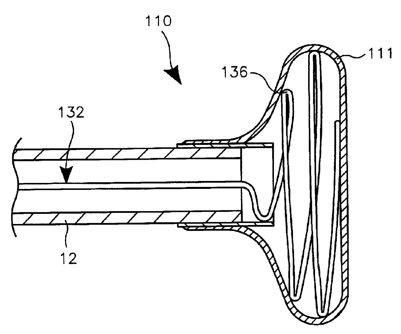
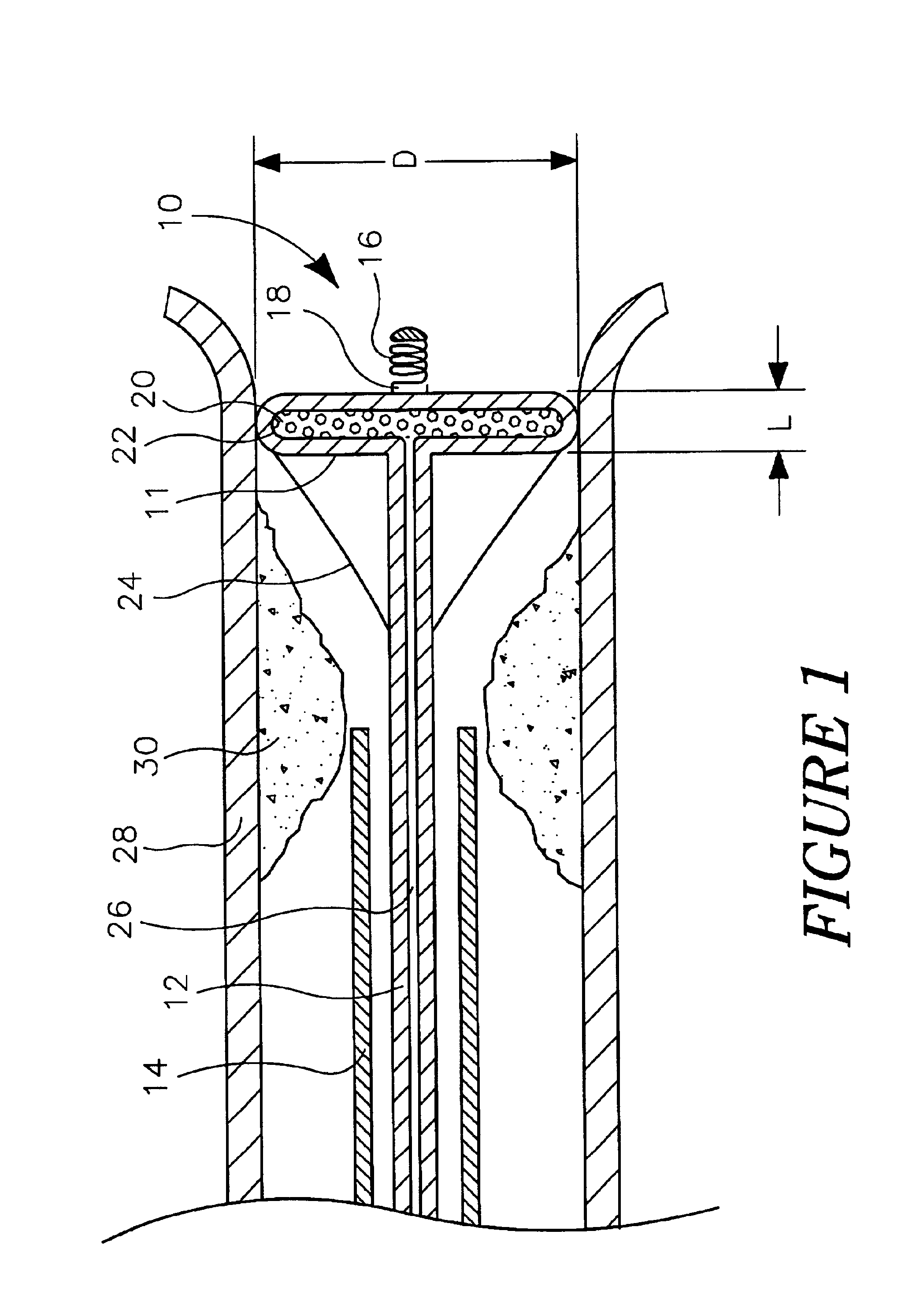
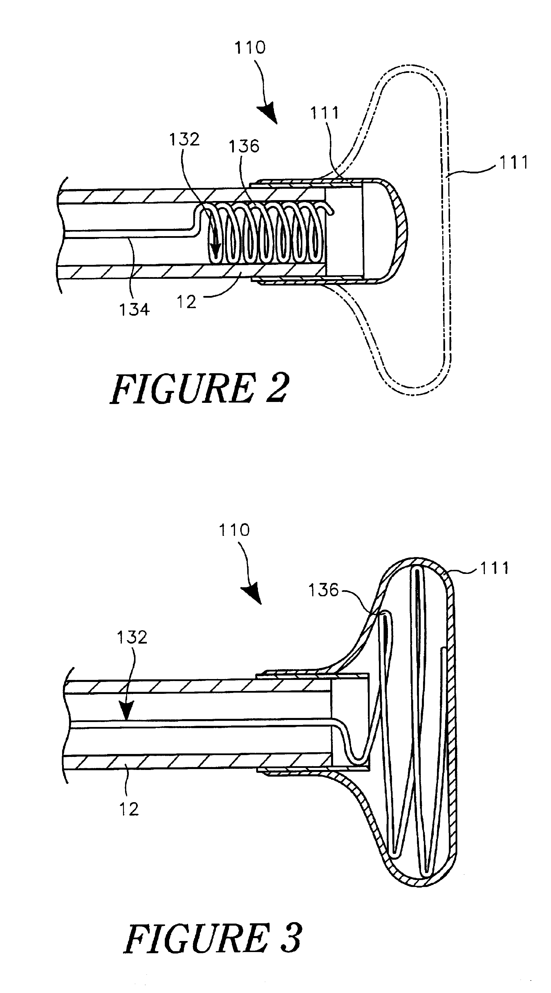
[0012]A number of diagnostic and therapeutic interventions may result in the release of intravascular embolic debris. Several filtering devices have been developed to capture and / or remove this debris. However, some procedures and intravascular locations are not readily accessible to traditional filters. FIG. 1 is a cross sectional plan overview of a disc-shaped distal protection filter device 10. Filter device 10 includes a filter 11 attached to an elongate shaft 12. The design of filter device 10 permits filtering at intravascular locations that might otherwise not be readily accessible by traditional filters.

[0013]Shaft 12 may comprise a guidewire or intravascular catheter, similar to any number of those known in the art or as ...


PUM


Abstract

Distal protection filter and method of using the same. A distal protection filter may be coupled to an elongate shaft. The filter includes a filter material coupled to a filter frame. The shape of the filter may be generally cylindrical or disc shaped. The filter material may capture embolic debris generated during an intravascular intervention.

Description

BACKGROUND OF THE INVENTION[0001]1. Field of the Invention[0002]The present invention pertains to filtering devices. More particularly, the present invention pertains to devices and methods for filtering embolic debris from a blood vessel.[0003]2. Description of the Related Art[0004]Occluded, stenotic, or narrowed blood vessels may be treated with a number of relatively non-invasive medical procedures. For example, occlusions of blood vessels near the heart may be treated by percutaneous transluminal angioplasty (PTA), percutaneous transluminal coronary angioplasty (PTCA), atherectomy, etc. Similarly, a number of occlusions may occur in other blood vessels located a distance away from the heart. For example, an occlusion may occur within the renal artery between the abdominal aorta and the kidney. Because this vascular region is relatively short in length, an appropriate intervention may necessitate design modifications of current intravascular devices.[0005]When treating occluded o...

Claims


Application Information

Patent Timeline
IPC IPC(8): A61F2/01A61B17/22A61B17/00A61M25/00
CPCA61F2/013A61F2/01A61F2002/018A61F2230/0006A61F2230/0067A61F2230/0078A61F2/0108
Inventor UNGS, MARK T.
Owner BOSTON SCI SCIMED INC
Why Eureka
Try Eureka