Method of weldbonding

a technology of weldbonding and welds, which is applied in the field of weldbonding, can solve the problems of reducing the quality of the weld, and achieve the effects of reducing the imperfections of the weld, improving the material properties of the weld pool, and reducing the cracking of the weld

Inactive Publication Date: 2005-08-23
EDISON WELDING INSTITUTE INC
View PDF30 Cites 11 Cited by
  • Summary
  • Abstract
  • Description
  • Claims
  • Application Information

AI Technical Summary

Benefits of technology

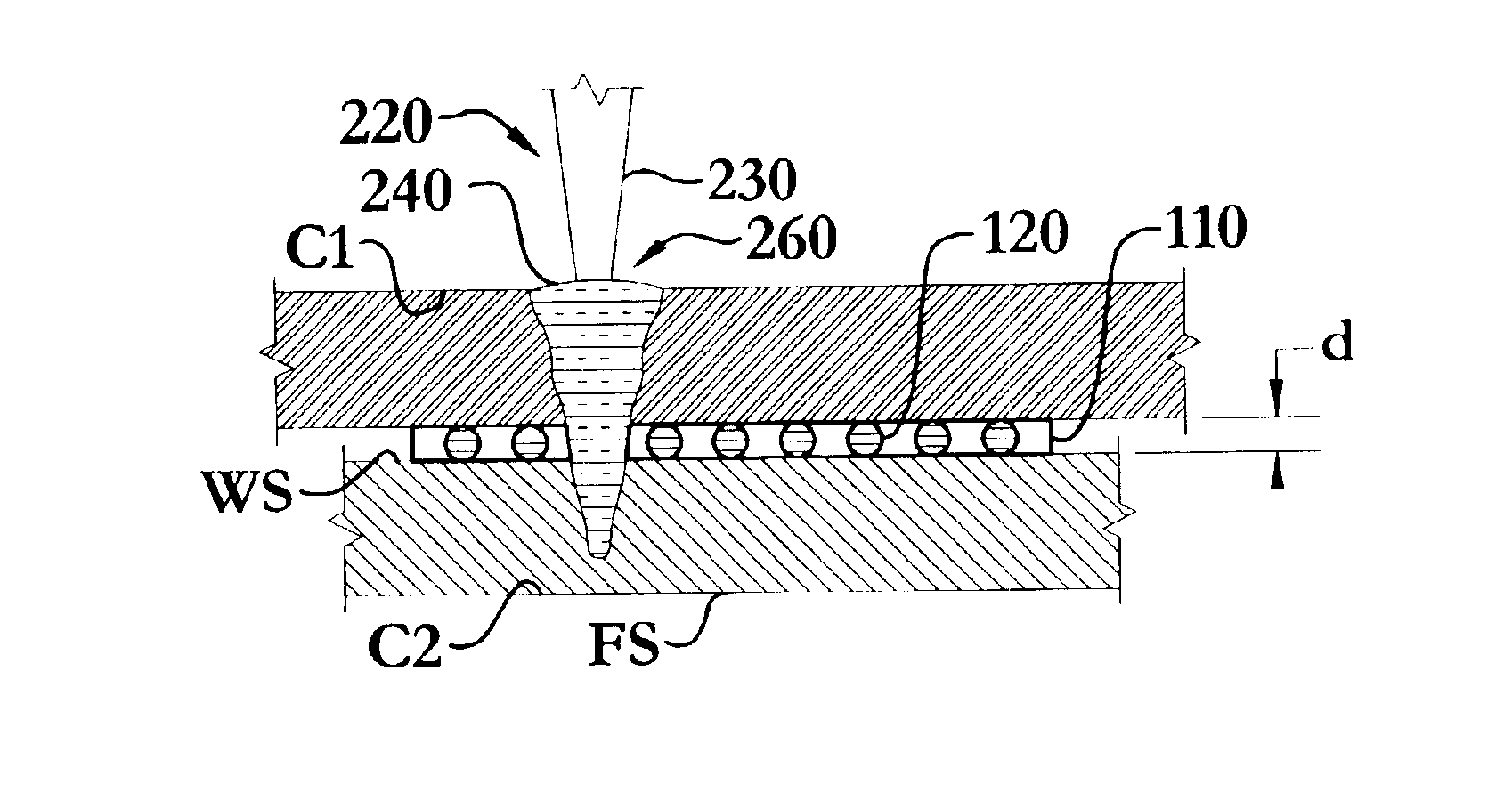
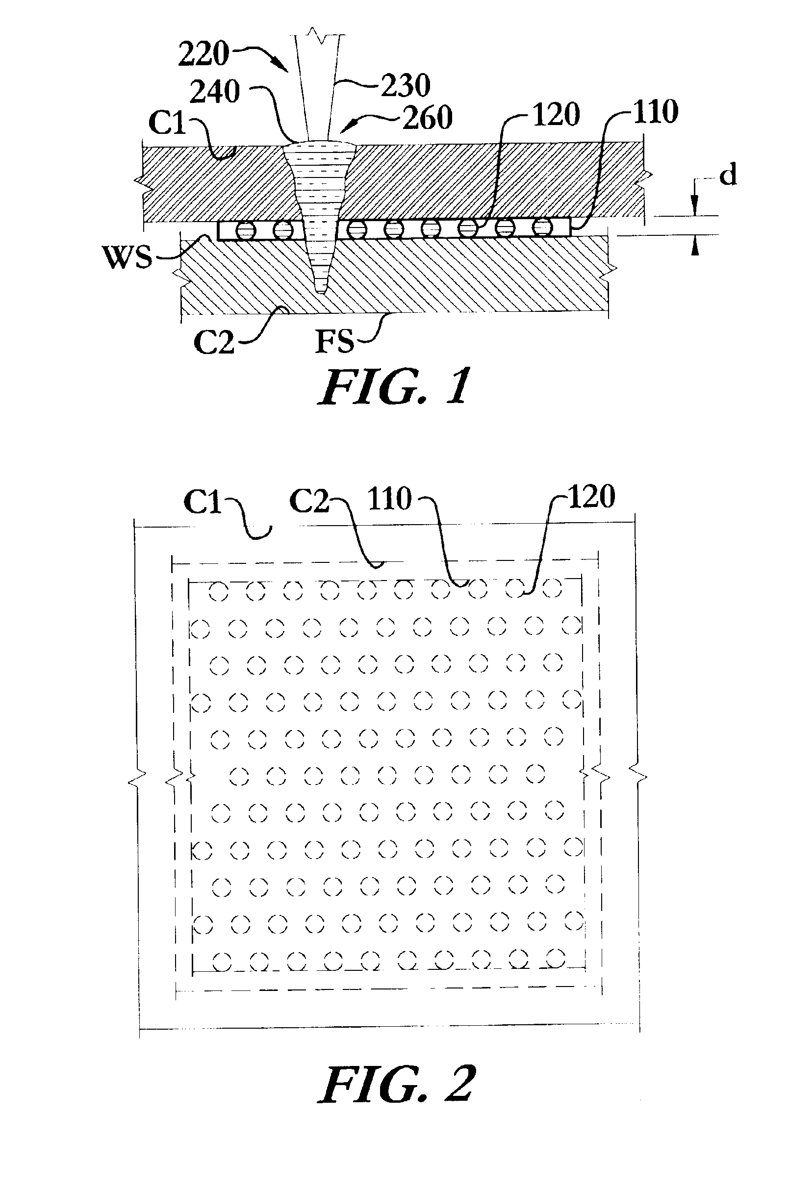
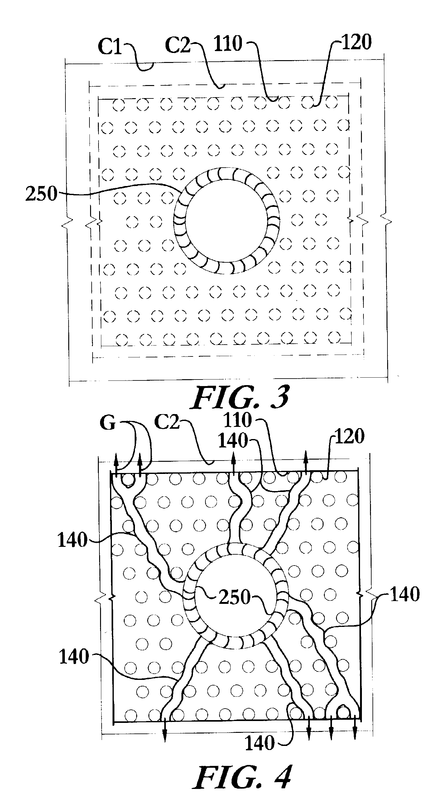
[0015]In one of the many preferable configurations, the method of weldbonding incorporates, among other steps, applying an adhesive between a first rigid material and a second rigid material, bringing the first rigid material and the second rigid material into close proximity and maintaining their relative positions with a retaining means, sweeping a weld area with a welding means, and providing a plurality of gas release and gap sustaining inclusion bodies between the components. The plurality of gas release and gap sustaining inclusion bodies allow at least one gas generated during the weldbonding process to escape to atmosphere substantially without passing through the weld pool and thereby reducing the quality of the weld. The at least one gas creates at least one passageway around the plurality of gas release and gap sustaining inclusion bodies between the first rigid material component and the second rigid material component allowing the at least one gas to escape to atmosphere. The new and novel concept of a plurality of gas release and gap sustaining inclusion bodies allowing gas to escape the weld area by creating at least one passageway is not limited to the field of weldbonding and may be effectively applied in the general field of welding.
[0019]In addition to minimizing adhesive flow into the weld area, the importance of the presence or absence of adhesive in the weld area is further reduced by providing for a method of venting such gas and gaseous byproducts of the welding process as may occur. These gas and gaseous byproducts include, byway of example and not limitation, vaporized elements from the materials to be joined and from any coating that may be present on the materials. Additionally, these gases and gaseous byproducts could be supplemented, by way of example and not limitation, by combustion or vaporization products from any adhesive or other material that may be in the weld area. The instant invention provides for inclusion bodies between the surfaces of the materials to be joined. These inclusion bodies tend to maintain a gap between the materials to be joined to allow the lateral release of such gas or gaseous byproducts that may be generated.
[0023]In addition to improving the weldbonding method by allowing for the escape of the at least one gas, this method also improves the weld quality by introducing a crack-reducing additive to the weld area. The crack-reducing additive acts to slow down the solidification of the weld pool thereby reducing the likelihood of cracks in the weld pool due to rapid cooling. This is particularly important when welding aluminum alloys, many of which are solidification crack sensitive. Addition of the crack-reducing additive may eliminate the need to use aluminum alloy filler materials. In one of many embodiments, more specifically when weldbonding aluminum alloys including the 6000 series of alloys, the crack-reducing additive is a silicon rich material. The crack-reducing additive may be introduced into the weld area in a number of methods. For example, but not limitation, the crack-reducing additive may be introduced to the weld area in powder form, wire form, foil form, tablet form, or as an integral additive within the adhesive. Alternatively, the inclusion bodies may be made of the crack-reducing additive so as to introduce additional crack-reducing additive into the weld area when they are melted.
[0025]Welding means as they are disclosed and claimed in the instant invention is intended to include various types of welding, including by way of example and not limitation, resistance welding, laser welding, conductive heat spot welding, conduction arc / plasma welding, ultrasonic welding, through transmission infrared welding, and electron beam welding. In one of numerous variations of the present method the welding means is a laser beam having a variable intensity. The method of the present invention may further include the step of varying the intensity of the laser beam to produce a plurality of heating phases incorporating at least an ablating phase, a welding phase, and an annealing phase, to both prepare the weld area and heat treat the weld pool. The ablating phase serves to ablate a plurality of materials from the weld area prior to the welding phase. The plurality of materials to be ablated may include; but is not limited to; coatings; adhesives; alloying elements of the rigid materials; and grease, dirt, or other impurities in the weld area. These materials are typically removed from the weld area by flaring out of the weld area or by vaporization when exposed to the welding means. The plurality of heating phases serves to improve the material properties of the weld pool and the heat-affected zone, and reduce the imperfections in the weld in a number of ways. For example, the ablating phase, welding phase, and annealing phase may be configured to control the heating rate, cooling rate, and critical microstructure transformation temperatures of the local weld area, in addition to preparing the weld area as previously described. Such control allows the maintenance of the weld pool and heat-affected zone within predetermined temperature ranges for predetermined times. Additionally, this allows control of the solidification time of the weld pool, thereby reducing weld cracking. A preferred embodiment utilizes a single laser beam of variable intensity and pulse rate to achieve the plurality of heating phases. Similar results may be obtained if the welding means were virtually any high-energy beam. The new and novel concept of an ablating phase is not limited to weldbonding and may be effectively applied in the general field of welding.
[0026]A further variation of the preceding embodiment, incorporates the strategic use of shielding gases to improve the weld quality and appearance. In one such variation, the shielding gas used during the ablating phase described above is such that it accelerates and / or fuels the ablatement of the plurality of materials. An alternative inert gas shielding gas may then be used during the welding and annealing phases to protect the weld and achieve the desired appearance. The novel use of a shielding gas to accelerate the ablatement phase is not limited to weldbonding and may be effectively applied in the general field of welding.
[0027]The method of weldbonding of the present invention may be applied to virtually any rigid components that may be weldbonded. The method has significant applications wherein the plurality of rigid material components, the first rigid material component, and the second rigid material component are composed of metal or metal alloys. Additionally, the present method may be used in joining dissimilar materials. This method significantly advances the field of weldbonding aluminum alloys, and more specifically the widely used 6000 series of aluminum alloy. The method also has significant advantages for joining coated materials.

Problems solved by technology

The plurality of gas release and gap sustaining inclusion bodies allow at least one gas generated during the weldbonding process to escape to atmosphere substantially without passing through the weld pool and thereby reducing the quality of the weld.
However, these techniques all add various complications to weldbonding that underscore that an optimal weldbonding method, as in the instant invention, will perform well both with, and without, adhesive in the weld area.

Method used


Image

  • Method of weldbonding
  • Method of weldbonding
  • Method of weldbonding

Examples


Embodiment Construction

[0041]The method of weldbonding of the instant invention enables a significant advance in the state of the art. The preferred embodiments of the apparatus accomplish this by new and novel methods that are performed in unique and novel ways and which demonstrate previously unavailable but preferred and desirable capabilities.

[0042]The detailed description set forth below in connection with the drawings is intended merely as a description of the presently preferred embodiments of the invention, and is not intended to represent the only method and form in which the present invention may be constructed or utilized. The description sets forth the designs, functions, means, and methods of implementing the invention in connection with the illustrated embodiments. It is to be understood, however, that the same or equivalent functions and features may be accomplished by different embodiments that are also intended to be encompassed within the spirit and scope of the invention.

[0043]With refe...


PUM

PropertyMeasurementUnit
separation distanceaaaaaaaaaa
areaaaaaaaaaaa

Abstract

An improved method of weldbonding utilizing inclusion bodies, placed directly between materials to be bonded or included in a weldbonding adhesive. The inclusion bodies maintain a gap between the materials to be welded which provides a gas releasing egress route to disperse the gas and gaseous byproducts produced during welding. This egress route substantially prevents the gases and gaseous byproducts from being expelled through the weld pool and the resultant degradation of the quality of the weld pool, particularly with coated materials, partial penetration welds, and such materials as 6000 series aluminum. The method further comprises an optional step of including a crack-reducing additive, applied either directly to the materials to be welded or included in the adhesive. A laser weldbonding embodiment may use a plurality of phased heat cycles to reduce weld imperfections, and enhance the effects of the adhesive and optional crack-reducing additive.

Description

TECHNICAL FIELD[0001]The present invention relates to the field of weldbonding; particularly, to a method of weldbonding articles resulting in improved weld quality.BACKGROUND OF THE INVENTION[0002]Weldbonding, the process of joining materials with both welding and adhesive, offers numerous advantages over either welding or adhesive technology applied singly to materials joining. Among these advantages are stronger joints that reduce previous structural adhesive bonding limitations such as out-of-plane load-carrying capability, also commonly referred to as peel. Unfortunately, the development of weldbonding processes has been plagued with a number of problems.[0003]The first problem has been the tendency of an adhesive to act as a non-conductive layer between the parts to be welded. One solution to this problem, that of welding only through areas that contain no adhesive, limits the placement of adhesive and substantially increases the labor required in accurate adhesive and weld pl...

Claims


Application Information

Patent Timeline
Patent Type & Authority Patents(United States)
IPC IPC(8): B23K26/00B23K26/32B23K26/24
CPCB23K26/246B23K26/3206B23K26/3226B23K26/3233B23K26/3293B23K2203/10B23K2203/18B23K26/32B23K26/323B23K26/244B23K2101/34B23K2103/08B23K2103/10B23K2103/18B23K2103/50
Inventor ELY, KEVIN J.FRECH, TIMOTHY M.RITTER, GEORGE W.
Owner EDISON WELDING INSTITUTE INC
Why Eureka
Try Eureka