Filter device

a filter device and filter technology, applied in the direction of filtering separation, moving filter element filters, separation processes, etc., can solve the problem of compact structure of filter devices, and achieve the effect of increasing the purity of filtrates

Inactive Publication Date: 2005-08-23
HYDAC FILTERTECHNIK GMBH
View PDF8 Cites 6 Cited by
  • Summary
  • Abstract
  • Description
  • Claims
  • Application Information

AI Technical Summary

Benefits of technology

[0004]Objects of the present invention are to provide an improved filter device for increased purity of the filtrate with every specific filtration grade of the filter elements, during the entire filtration process.

Problems solved by technology

This filter device is very compact in structure and in general requires a small number of structural components.

Method used


Image

  • Filter device
  • Filter device
  • Filter device

Examples


Embodiment Construction

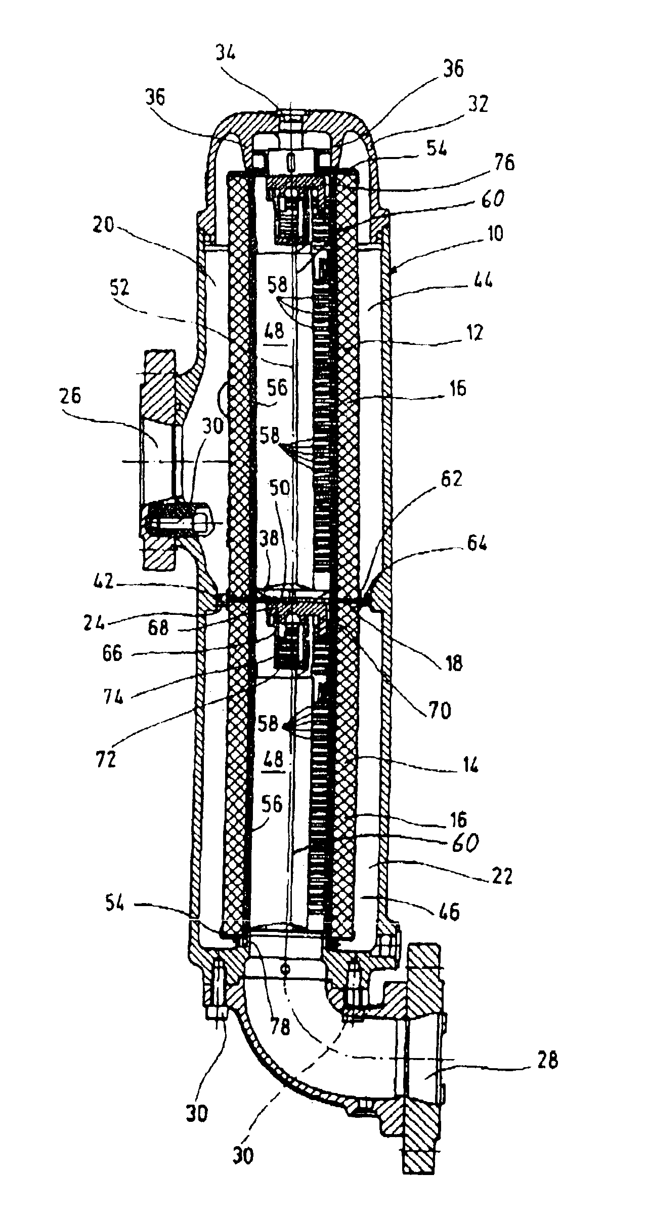
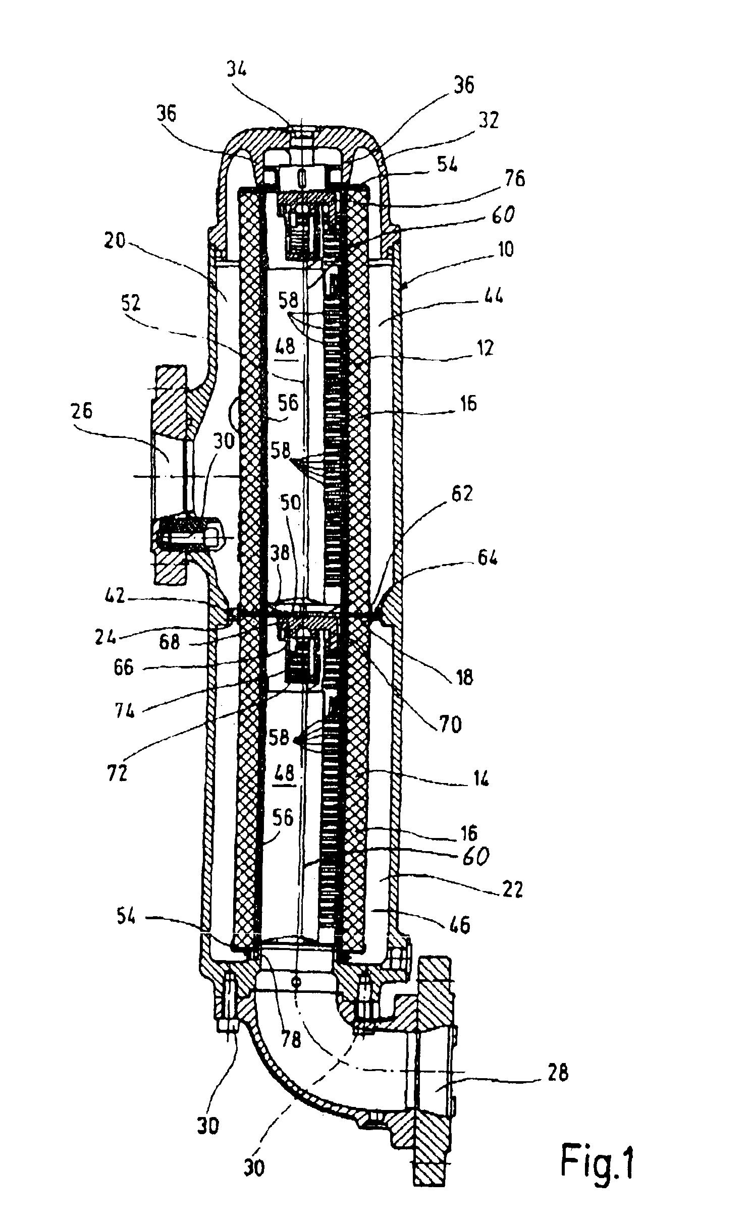
[0018]The filter device shown in FIG. 1 has a filter housing 10. Two filter elements 12,14 are mounted one above the other in the filter housing. The filter elements in question 12,14 have different filtration grades. These filtration grades may be determined by use of different filter materials 16 or the same filter materials 16 with different permeability values. The filter materials 16 may be in the form of hollow cylinders, but preferably have pleated filter matting, that is, matting folded like an accordion. In particular, filter materials 16 of a plastic substance may be employed in this application.

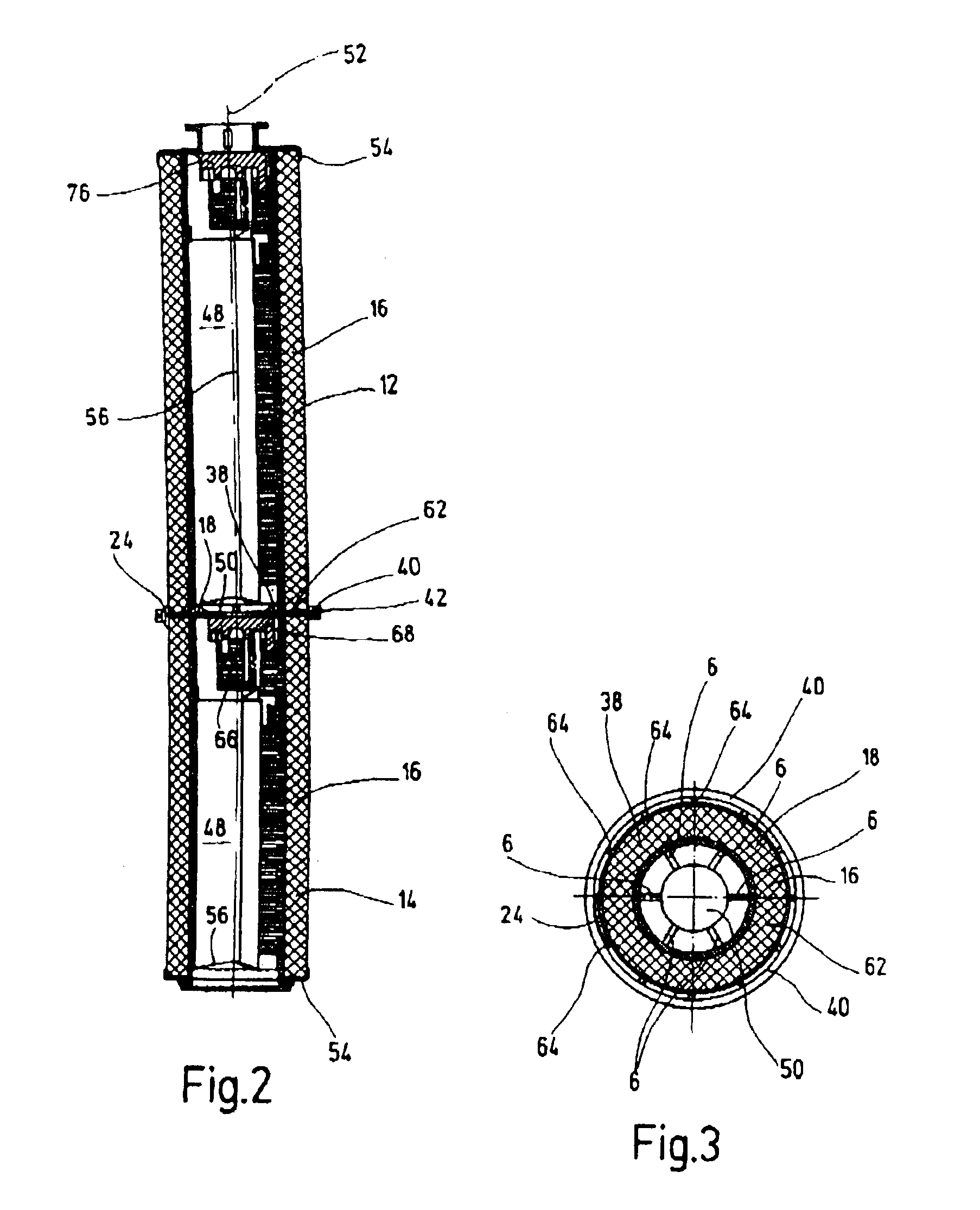
[0019]The two filter elements 12,14 are partly separated from each other spatially and with respect to external conduct of fluid by a separating device 18. An enlarged top view of the separating device 18 is presented in FIG. 3. For a fluid-conducting connection between the two adjacent filter spaces 20,22, this separating device has a passage point 24 upstream from the filter mate...


PUM

PropertyMeasurementUnit
pressureaaaaaaaaaa
lengthsaaaaaaaaaa
closing pressureaaaaaaaaaa

Abstract

A filter device includes a filter housing (10) in which at least two filter elements (12, 14) with differing filter grades of filter material (16) are arranged. The filter elements are partially separated from each other by a separating device (18), with a through channel (24) of predetermined cross-section for a hydraulic connection between neighboring filter chambers (20, 22),. The filter chambers arranged prior to the filter materials (16) in the flow direction of the fluids for filtering. The filter device permits a combination of main- and side-stream filters in the smallest possible space, whereby very good purity levels for the filtered fluid are nevertheless achieved.

Description

FIELD OF THE INVENTION[0001]The present invention relates to a filter device with a filter housing in which at least two filter elements with filter materials of different filtration grades are mounted. The filter elements are partly separated from each other by a separating device having a passage point of assignable cross-section for a fluid-conducting connection of adjacent filter spaces. The filter spaces are situated upstream from the filter materials in the direction of flow of the fluid to be cleaned.BACKGROUND OF THE INVENTION[0002]U.S. Pat. No. 3,344,923 describes a filter unit with two filter elements in the form of hollow cylinders. Both elements are of the same filtration grade. The filter elements are mounted in a common housing so that their longitudinal axes are in alignment. The two filter elements are separated from each other by a separating device extending transversely to the longitudinal axes. At the same time, the filter space (unfiltered fluid space) situated ...

Claims


Application Information

Patent Timeline
Patent Type & Authority Patents(United States)
IPC IPC(8): B01D29/15B01D29/13B01D35/147B01D35/14B01D29/07B01D29/50B01D29/54B01D35/157B01D46/52
CPCB01D29/15B01D35/147B01D29/54B01D35/157B01D35/303B01D2201/188
Inventor SANN, NORBERTREIK, MARTINHENNES, STEFANLEICHNER, KARL-HEINZ
Owner HYDAC FILTERTECHNIK GMBH
Why Eureka
Try Eureka