Commutating rotary switch

a rotary switch and rotary switch technology, applied in current collectors, dynamo-electric machines, dynamo-electric components, etc., can solve the problems of increasing the wear of brushes and especially tight space of hand tools, and achieve the effect of conserving structural spa

Inactive Publication Date: 2005-08-23
HILTI AG
View PDF5 Cites 12 Cited by
  • Summary
  • Abstract
  • Description
  • Claims
  • Application Information

AI Technical Summary

Benefits of technology

[0006]The object of the invention is to provide a turning-pivoting commutating rotary switch with brush holders that conserves structural spa...

Problems solved by technology

Such a space is especially tight in hand tools.
Heavy brush sparking results through the brush guide du...

Method used


Image

  • Commutating rotary switch
  • Commutating rotary switch

Examples


Embodiment Construction

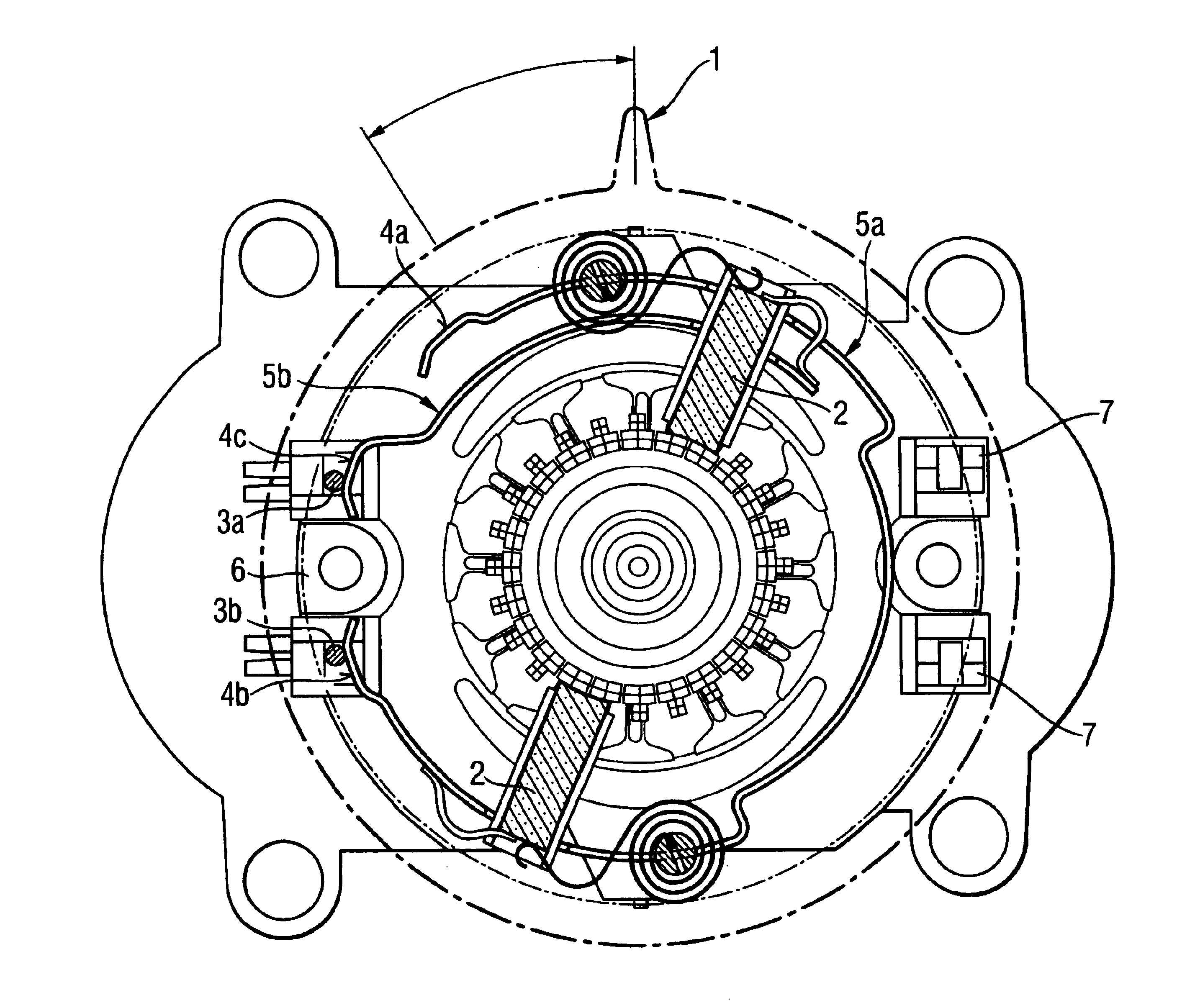
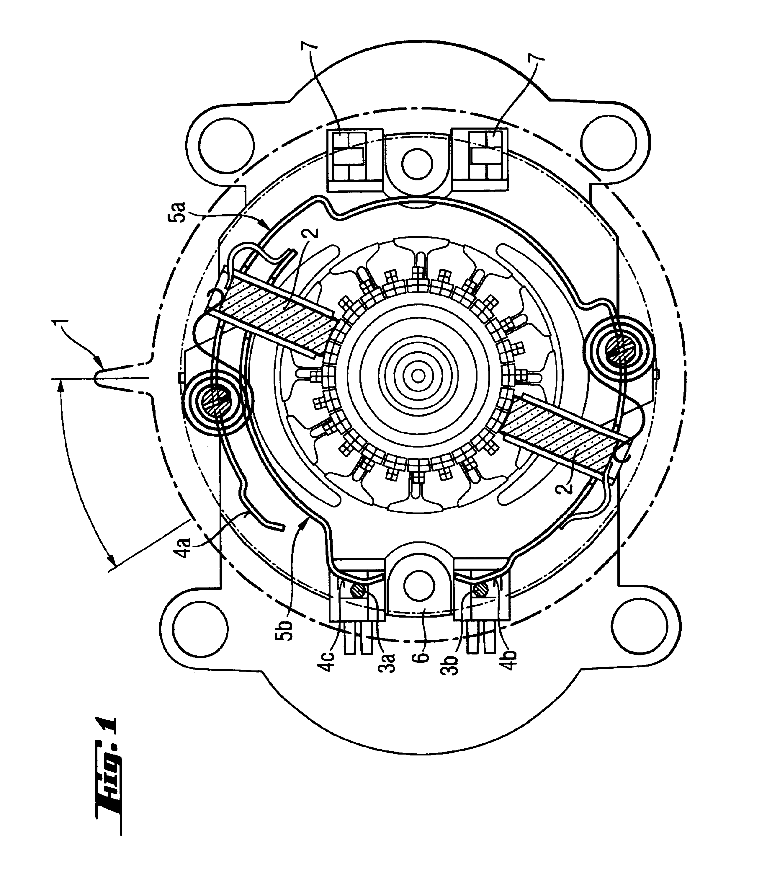
[0016]FIG. 1 shows a virtual turning-pivoting commutating rotary switch 1 with brush guides 2 for reversal of rotational direction of an universal motor (represented open on the commutator side) has two stator contacts 3a, 3b. The stator contacts 3a, 3b each make contact at at least one contact point 4a, 4b, 4c of a contact rail 5a, 5b represented herein as running partially peripherally in the form of partially resilient contact flat springs, that are conducting connected with two diametrically opposing brush guides 2. A contact rail 5a extends with two contact points 4a, 4b over a half periphery of approximately 300°. The other contact rail 5b has precisely one contact point that alternating switches to the two contact points 3a, 3b. Both contact rails 5a, 5b are radially separated and disposed axially in one plane. Both stator contacts 3a, 3b, with which at least one contact point 4a, 4b, 4c can be rotatably switchably assigned on each partially peripheral contact rail 5a, 5b, ar...


PUM


Abstract

A turning-pivoting commutating rotary switch (1) with brush guides (2) for reversing the direction of rotation of a universal motor, which has two stator contacts (3a, 3b) each making contact with a contact rail (5a, 5b) running partially peripherally at at least one contact point (4a, 4b, 4c), which are conducting connected with the two diametrically opposing brush guides (2), wherein a contact rail (5a) with two contact points (4a, 4b) extends over at least a half periphery and wherein both stator contacts (4a, 3b), at which at least one contact point (4a, 4b, 4c) can be rotatably switchable at a contact rail (5a, 5b) running partially peripherally, are arranged on only one side of the stator (6).

Description

BACKGROUND OF THE INVENTION[0001]The invention concerns a turning-pivoting commutating rotary switch with brush guides for reversing the direction of rotation of a universal electrical motor, preferably for use in hand tool machines or power tools.[0002]Conventionally, a turning-pivoting brush holder with brush guides configured as a turning-pivoting commutating rotary switch for reversing rotational direction features two diametrically opposed stator contacts, each making contact with two diametrically opposing, partially peripheral contact bars at two contact points, which are conducting connected with the two diametrically opposing brush guides. Consequently, upon pivoting, the commutator rotary switch, on the one hand, by the intermittent contact of the contact points, with the stator contacts, the armature coil pole is reversed, and, on the other hand, the brush guides pivot out of the polar plane as a factor of the direction of rotation. The invention relates to such a commuta...

Claims


Application Information

Patent Timeline
IPC IPC(8): H01R39/00H02K23/02H02K23/18H02K23/66H01R39/59H02K5/22H01R39/18H02K13/00
CPCH01R39/59H02K23/18H02K23/66H02K5/225
Inventor BRAML, GEORGLUBKERT, ERNST-RUDOLF
Owner HILTI AG
Why Eureka
Try Eureka