Electronic endoscope with three-dimensional image capturing device

a technology of three-dimensional image and endoscope, which is applied in the direction of optical radiation measurement, distance measurement, luminescent dosimeter, etc., can solve the problems of reduced stereoscopic quality of three-dimensional image, difficult to obtain a three-dimensional image with a high accuracy, and thick flexible tube diameter, etc., to achieve the effect of reducing the diameter of the flexible tub

Inactive Publication Date: 2005-08-23
RICOH IMAGING COMPANY
View PDF17 Cites 71 Cited by
  • Summary
  • Abstract
  • Description
  • Claims
  • Application Information

AI Technical Summary

Benefits of technology

[0006]Therefore, an object of the present invention is to reduce the diameter of the flexible tube in the electronic endoscope provided with the three-dimensional image capturing device.

Problems solved by technology

In this electronic endoscope, if the distance between the pair of light-receiving optic fibers is short, the stereoscopic quality of the three-dimensional image is reduced, and it is difficult to obtain a three-dimensional image with a high accuracy.
However, this causes the diameter of the flexible tube to become thick.

Method used


Image

  • Electronic endoscope with three-dimensional image capturing device
  • Electronic endoscope with three-dimensional image capturing device
  • Electronic endoscope with three-dimensional image capturing device

Examples


first embodiment

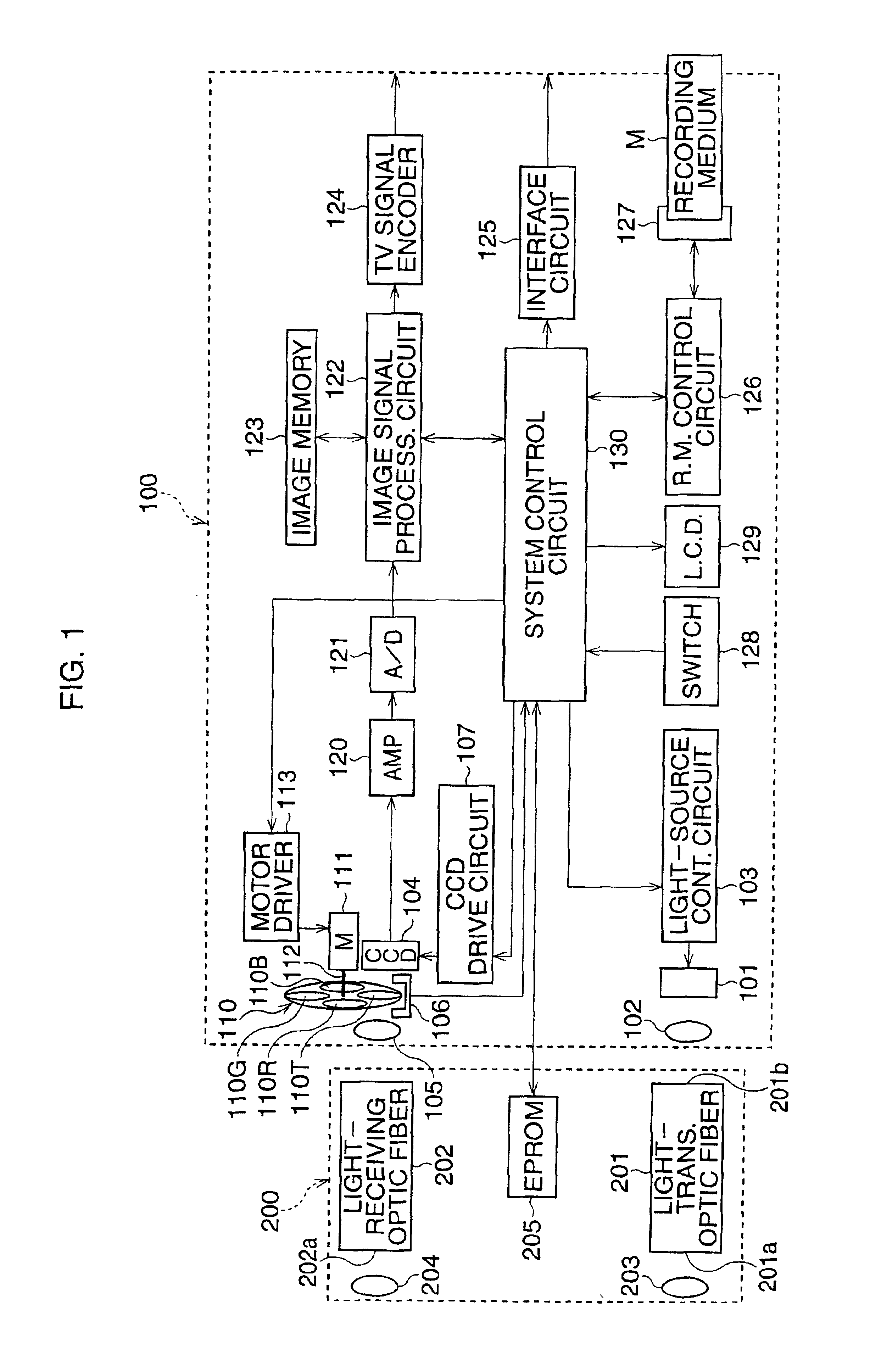
[0018]FIG. 1 shows a general construction of the inside of an electronic endoscope, which is the present invention.

[0019]The electronic endoscope has a housing 100 and a flexible tube 200, which is connected to the housing 100. In the flexible tube 200, a probe, which is inserted into a body, is formed in an elongated slender form and is flexible; the probe is shown as a rectangle in the drawing.

[0020]In the flexible tube 200, a light-transmitting optic fiber 201 and a light-receiving optic fiber 202, which have the same length, are housed. The light-transmitting optic fiber 201 transmits a distance-measuring light beam, which is irradiated to a subject or an observed portion in the body. The light-receiving optic fiber 202 transmits a reflected light beam generated by the subject which receives the distance-measuring light beam. A lens 203 is disposed at an end of the flexible tube 200 to face an output end face 201a of the light-transmitting optic fiber 201. A lens 204 is also dis...

second embodiment

[0061]As described above, the two-dimensional image and the three-dimensional image can be sensed simultaneously. Therefore, since the user can analyze the data of the three-dimensional image while observing the two-dimensional image, the data analysis can performed more accurately. Further, since the subject, i.e., an observed portion in a human body always stirs or slightly moves, simultaneous sensing is advantage.

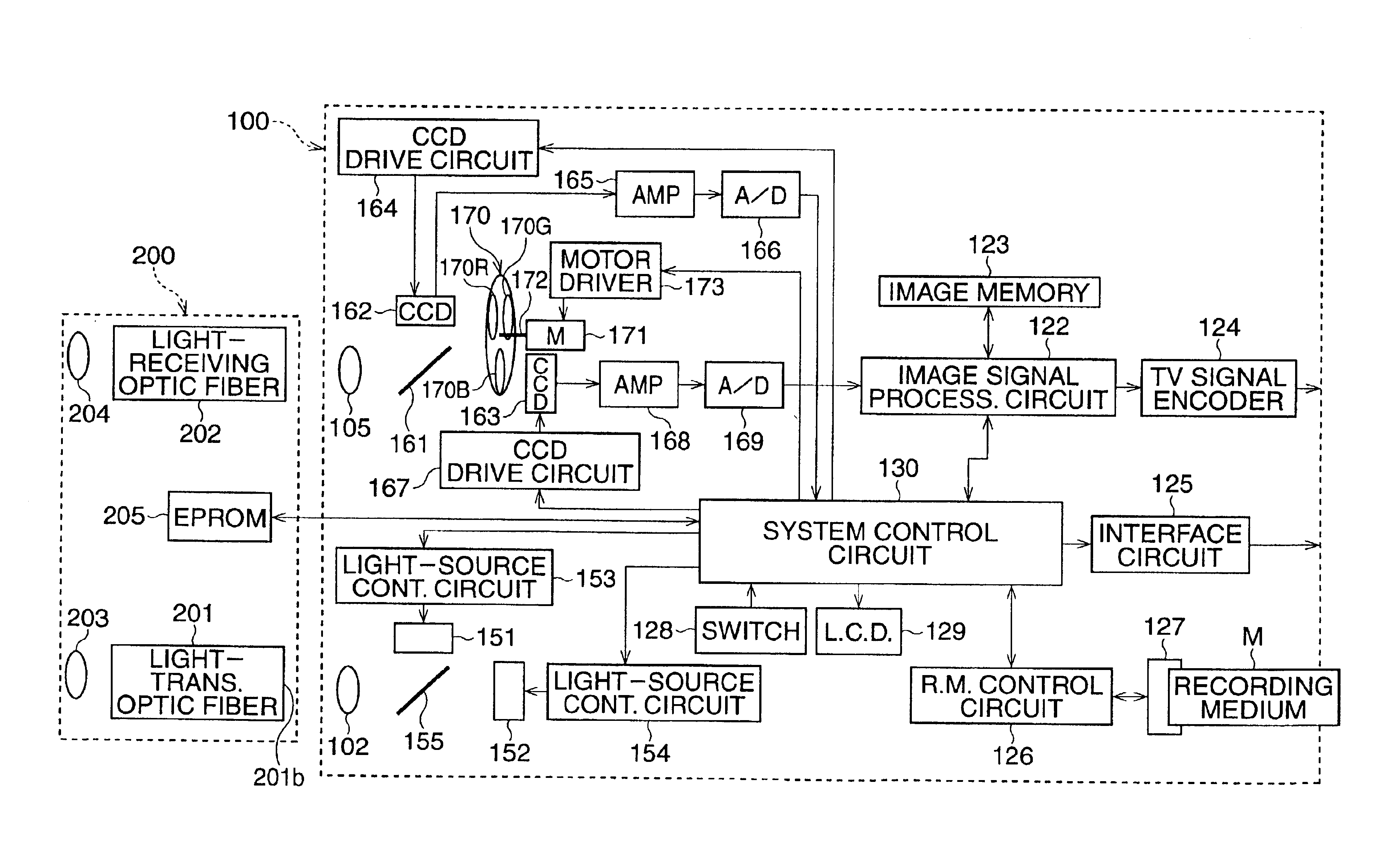
[0062]The distance-measuring light beam output by the distance measuring light source 151 and the distance-measuring light beam output by the illuminating light source 152 enter the light-transmitting optic fiber 201 through the single optic member 155, and the reflected light beams of the distance-measuring light beam and the illuminating light beam entering the housing 100 through the light-receiving optical fiber 202 are separated by the single optic member 161, and led to the CCDs 162 and 163. Thus, by the provision of the optic members 155 and 161, the portion clos...


PUM


Abstract

An electronic endoscope comprises a housing and a flexible tube. A light-transmitting optic fiber and a light-receiving optic fiber are provided in the flexible tube. A light source and an imaging device are provided in the housing. The light source outputs a pulsed distance-measuring light beam, which is transmitted along the light-transmitting optic fiber, and irradiated to a subject. A reflected light beam generated by the subject due to the distance-measuring light beam is transmitted along the light-receiving optic fiber, to enter the imaging device, in which an electric charge corresponding to the subject image (i.e., an image signal of a three-dimensional image) is accumulated. A timing of the accumulating operation of the imaging device is delayed depending on the lengths of the fibers.

Description

BACKGROUND OF THE INVENTION[0001]1. Field of the Invention[0002]The present invention relates to an electronic endoscope provided with a three-dimensional image capturing device by which a three-dimensional shape of an observed portion in a human body, which is a subject, is sensed.[0003]2. Description of the Related Art[0004]Conventionally, there is known an electronic endoscope of a type described above, which has a pair of light-receiving optic fibers in a flexible tube which is inserted in a human body. Namely, an image of the subject can be detected through the light-receiving optic fibers, and a three-dimensional image of the subject can be captured, using so-called triangulation (see “ENDOSCOPE TECHNOLOGY” (“POPULAR SIENCE 204” issued by Shokabo, pages 142-148)).[0005]In this electronic endoscope, if the distance between the pair of light-receiving optic fibers is short, the stereoscopic quality of the three-dimensional image is reduced, and it is difficult to obtain a three-...

Claims


Application Information

Patent Timeline
Patent Type & Authority Patents(United States)
IPC IPC(8): A61B1/04G02B23/24G02B23/26
CPCA61B1/042H04N2005/2255H04N23/555
Inventor YAMAMOTO, KIYOSHI
Owner RICOH IMAGING COMPANY
Why Eureka
Try Eureka