Optical element and manufacturing method thereof

Inactive Publication Date: 2005-08-23
DAI NIPPON PRINTING CO LTD
View PDF8 Cites 19 Cited by
  • Summary
  • Abstract
  • Description
  • Claims
  • Application Information

AI Technical Summary

Benefits of technology

[0006]It is therefore an object of the present invention to provide an optical element that ca

Problems solved by technology

The method for recording an image as interference fringes that has been widely used as an optical hologram producing method is at an advantage in that productivity is high because, in general, a reconstructed image with high resolution can be obtained and because an optical method is used, but it is at a disadvantage in that an image darkens because diffraction efficiency by interference fringes is poor when reconst

Method used


Image

  • Optical element and manufacturing method thereof
  • Optical element and manufacturing method thereof
  • Optical element and manufacturing method thereof

Examples


Embodiment Construction

[0075]The present invention will be hereinafter described on the basis of the embodiments shown in the figures.

§ 1. Basic Principle of the Present Invention

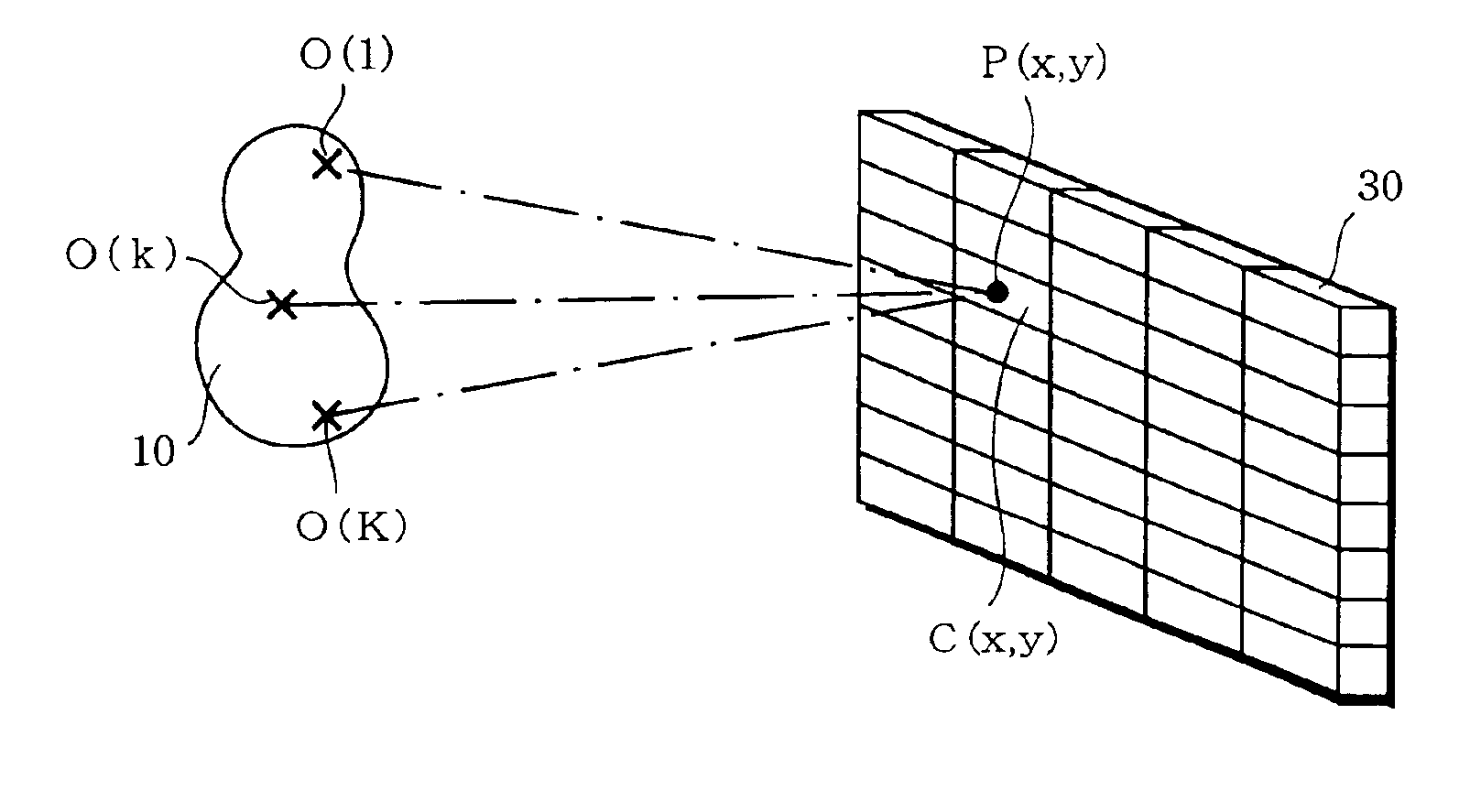
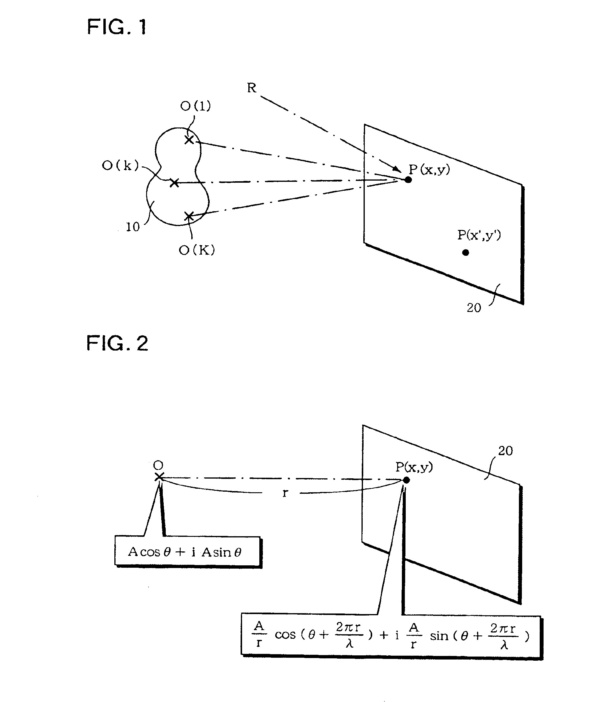
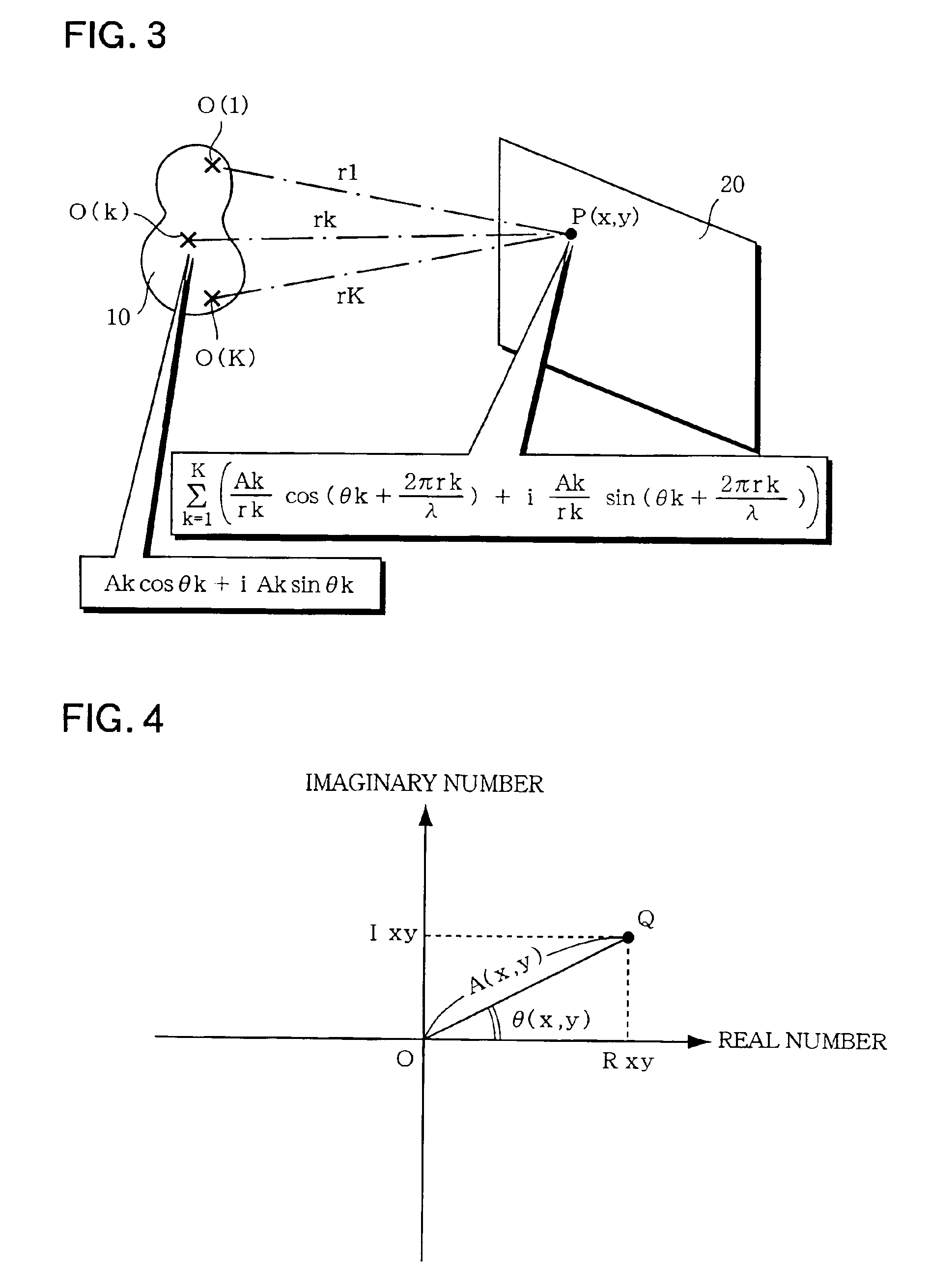
[0076]FIG. 1 is a perspective view that shows general holography in which an object image is optically recorded as interference fringes by use of reference light. When a stereoscopic image of an object 10 is recorded onto a recording medium 20, the object 10 is illuminated with light (normally, with a laser beam) having the same wavelength as reference light R, and interference fringes formed by object light from the object 10 and the reference light R on the recording medium 20 are recorded. Herein, if an XY coordinate system is defined on the recording medium 20, and attention is paid to an arbitrary point P(x, y) located at coordinates (x, y), the amplitude intensity of a composite wave resulting from interference between each object light from each point O(1), O(2), . . . , O(k), . . . , O(K) located on the object 10 and the ...


PUM


Abstract

An optical element has of a set a plurality of three-dimensional cells. A specific amplitude and a specific phase are defined in each individual cell. Each cell has a concave part formed by hollowing a part having an area corresponding to the specific amplitude by a depth corresponding to the specific phase. The individual cell has a specific optical property so that, when incident light is provided to the cell, emission light is obtained by changing an amplitude and a phase of the incident light in accordance with the specific amplitude and specific phase defined in the cell.

Description

[0001]This application is a divisional of application Ser. No. 09 / 932,006 filed on Aug. 17, 2001, now U.S. Pat. No. 6,618,190, claims the benefit thereof and incorporates the same by reference.BACKGROUND OF THE INVENTION[0002]The present invention relates to an optical element and a manufacturing method thereof and, more particularly, relates to an optical element capable of recording a stereoscopic image as a hologram and reconstructing the image, and a manufacturing method thereof.[0003]A holographic technique is conventionally known as a method for recording a stereoscopic image on a medium and reconstructing this image. A hologram produced by this method is used in various fields, such as ornamental art or anti-counterfeit seals. In order to optically produce the hologram, it is common to record the interference fringe between object light reflected from an object and reference light on a photosensitive medium. A laser beam superior in coherence is usually used as a light source...

Claims


Application Information

Patent Timeline
IPC IPC(8): G03H1/08G03H1/22G03H1/00G03H1/26
CPCG03H1/08G03H1/0841G03H1/0891G03H1/22G03H1/028G03H1/0808G03H2001/0858G03H2001/2223G03H2001/226G03H2210/40G03H2224/04G03H2240/13G03H2240/50
Inventor KITAMURA, MITSURUHAMANO, TOMOHISA
Owner DAI NIPPON PRINTING CO LTD
Why Eureka
Try Eureka