

Method and apparatus using reverse disk rotation to achieve slider contact with a disk surface
a technology of reverse disk rotation and slider, which is applied in the direction of mounting head within the housing, manufacturing head surface, instruments, etc., can solve the problems of limited control over the zth, and achieve the effects of high burnishing rate, rapid burnishing of sliders, and greater sensitivity
- Summary
- Abstract
- Description
- Claims
- Application Information
AI Technical Summary
Benefits of technology
Problems solved by technology
Method used
Image

Examples
Embodiment Construction
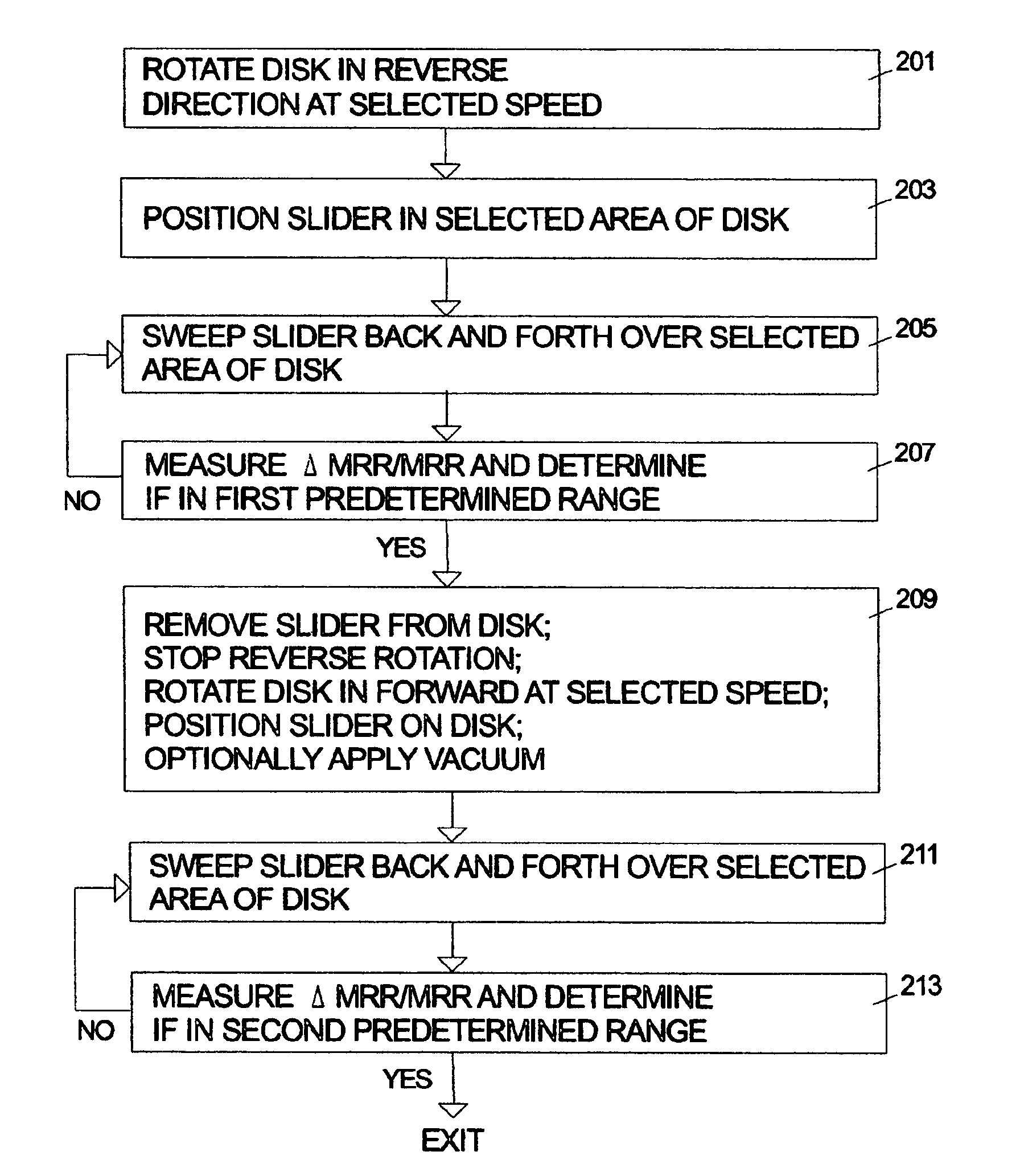
[0017]The air-bearing features of sliders are typically classified as positive pressure or negative pressure types. With either type, the air-bearing forms only when the disk is being rotated under the slider in the designated operational (“forward”) direction. The applicants have discovered that rotating the disk in backward or reverse direction allows the slider to be in contact with the disk, since no air-bearing is formed. The following will use the term “contact” to describe the relationship between the slider and the disk even though at high rotation rates there may be some periodic separation. The applicants use the slider contact with the disk to achieve a rapid burnishing of the slider without damaging the disk.
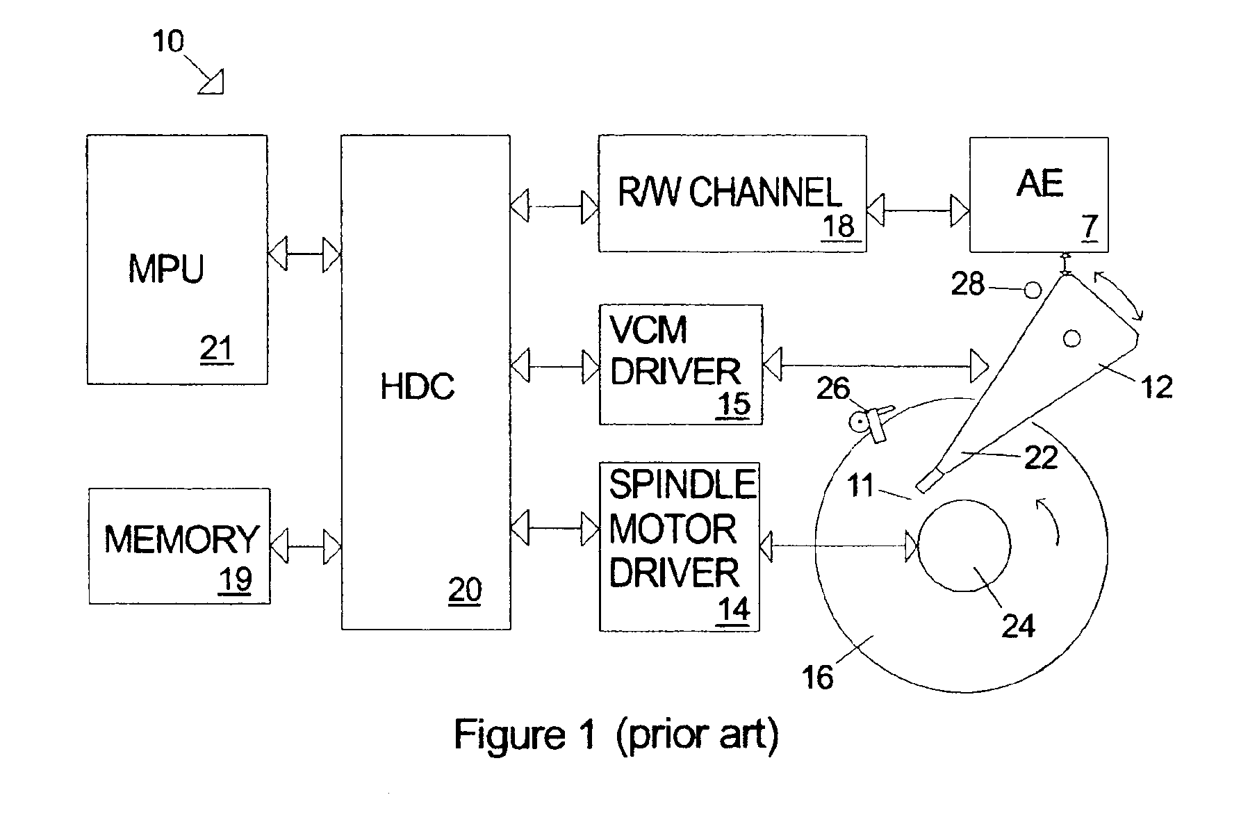
[0018]Typical spindle motors used in disk drives are highly controlled by the electronics and programming code, also called microcode or firmware, stored in the memory 19 shown in FIG. 1. The rate, duration and sequence of the pulses applied to the coils of the spind...
PUM
| Property | Measurement | Unit |
|---|---|---|
| area | aaaaa | aaaaa |
| ΔMRR/MRR | aaaaa | aaaaa |
| thickness | aaaaa | aaaaa |
Abstract
Description
Claims
Application Information