Packet size control technique

a technology of packet size and control method, applied in the field of packet transfer system, can solve the problems of difficult to effectively use available network bandwidth, blockage of sending processing, interrupting data processing in the receiving buffer, etc., and achieve the effect of improving data transfer throughput and reducing the period of tim

Inactive Publication Date: 2005-08-23
NEC CORP
View PDF18 Cites 60 Cited by
  • Summary
  • Abstract
  • Description
  • Claims
  • Application Information

AI Technical Summary

Benefits of technology

[0010]It is therefore an object of the present invention to provide a packet size control method and device allowing reduction in the period of time during which transmission is in a blocked state, which may occur in a case where a full send window of data is transmitted. In other words, the present invention provides a packet size control method capable of improving data transfer throughput.

Problems solved by technology

In data transmission through a network having a relatively large transfer delay, there has been known a problem such that the sending processing is blocked during a time period from transmission of a send window of data until reception of an acknowledgment (ACK) from a receiving side in the case where the product of bandwidth (or transfer rate) and round trip time (RTT) that is a delay time required for data round trip is greater than the size of a send window.
This makes it difficult to use available network bandwidth effectively and enable data transfer with efficient throughput.
However, the receiving side may temporarily delay the receiving processing to cause interrupt of data processing in the receiving buffer.
Further, an error in transmitting data may be caused by noise on the network to close a certain amount of receiving buffer area for an erroneous segment size of transfer data for re-transmission processing.
In these cases, part of data sent from the sending side exceeds the storage capacity of the receiving buffer, which may cause unnecessary re-transmission processing for a segment of correct incoming data.
However, if the transmitting side unilaterally up-sizes the send window as in the technique disclosed in the above-mentioned publication, the receiving side may not be able to receive part of data.
The above-mentioned other prior art techniques also put an emphasis on how to calculate the data size and disclose no effective solution to this problem.

Method used


Image

  • Packet size control technique
  • Packet size control technique
  • Packet size control technique

Examples


Embodiment Construction

[0026]Hereinafter, description will be made about an embodiment of the present invention with reference to the accompanying drawings.

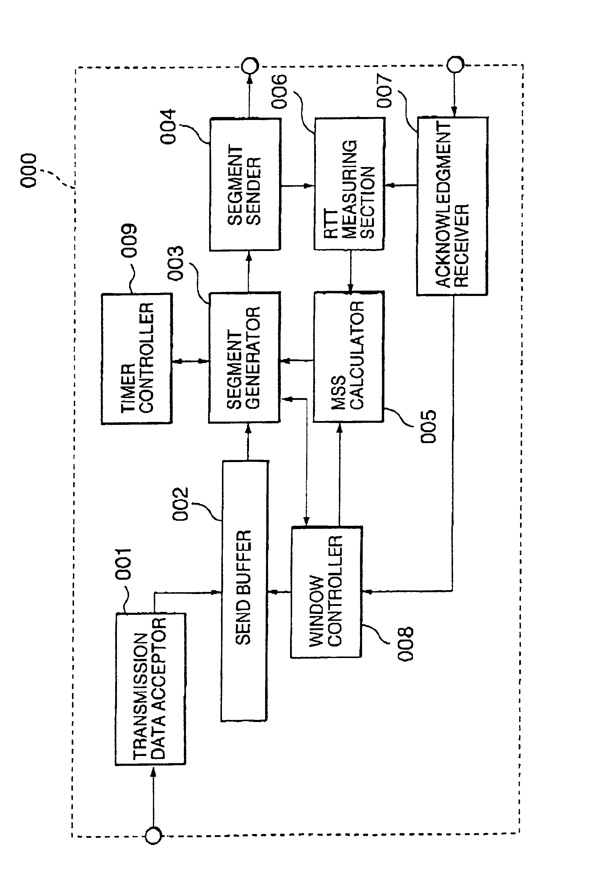
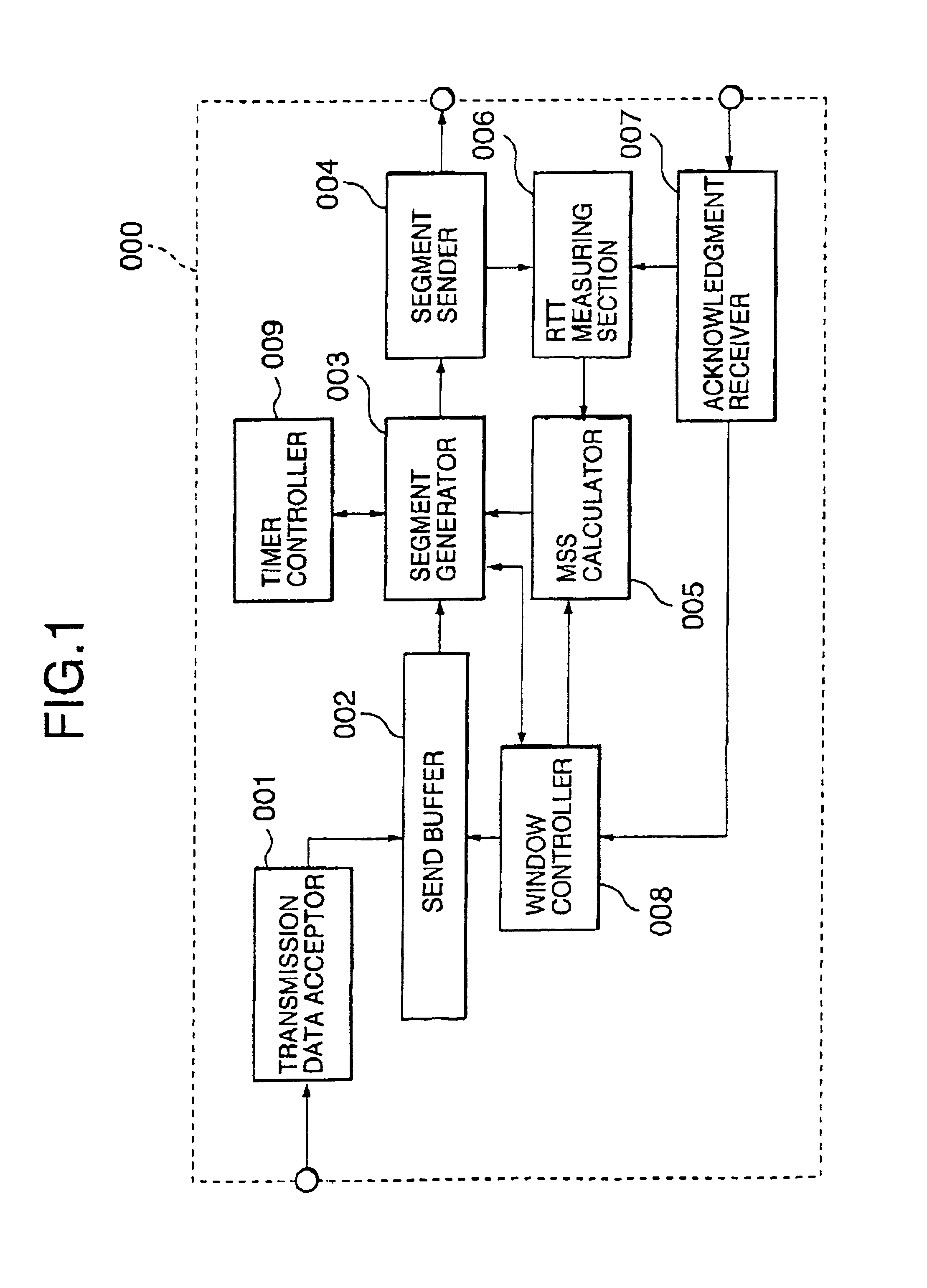
[0027]FIG. 1 shows a transport-layer protocol processing block 000 employing a packet data transfer method according to the present invention. Here, a block for re-transmission control is omitted from the processing block because no description thereof is needed for the embodiment. Of course, the transport-layer protocol processing block may perform re-transmission control in the packet data transfer method according to the present invention.

[0028]Referring to FIG. 1, the transport-layer protocol processing block 000 includes a send data acceptor 001, a send buffer 002, a segment generator 003, a segment sender 004, an MSS (Maximum Segment Size) calculator 005, an RTT measuring section 006, an acknowledgment receiver 007, a window controller 008, and a timer controller 009.

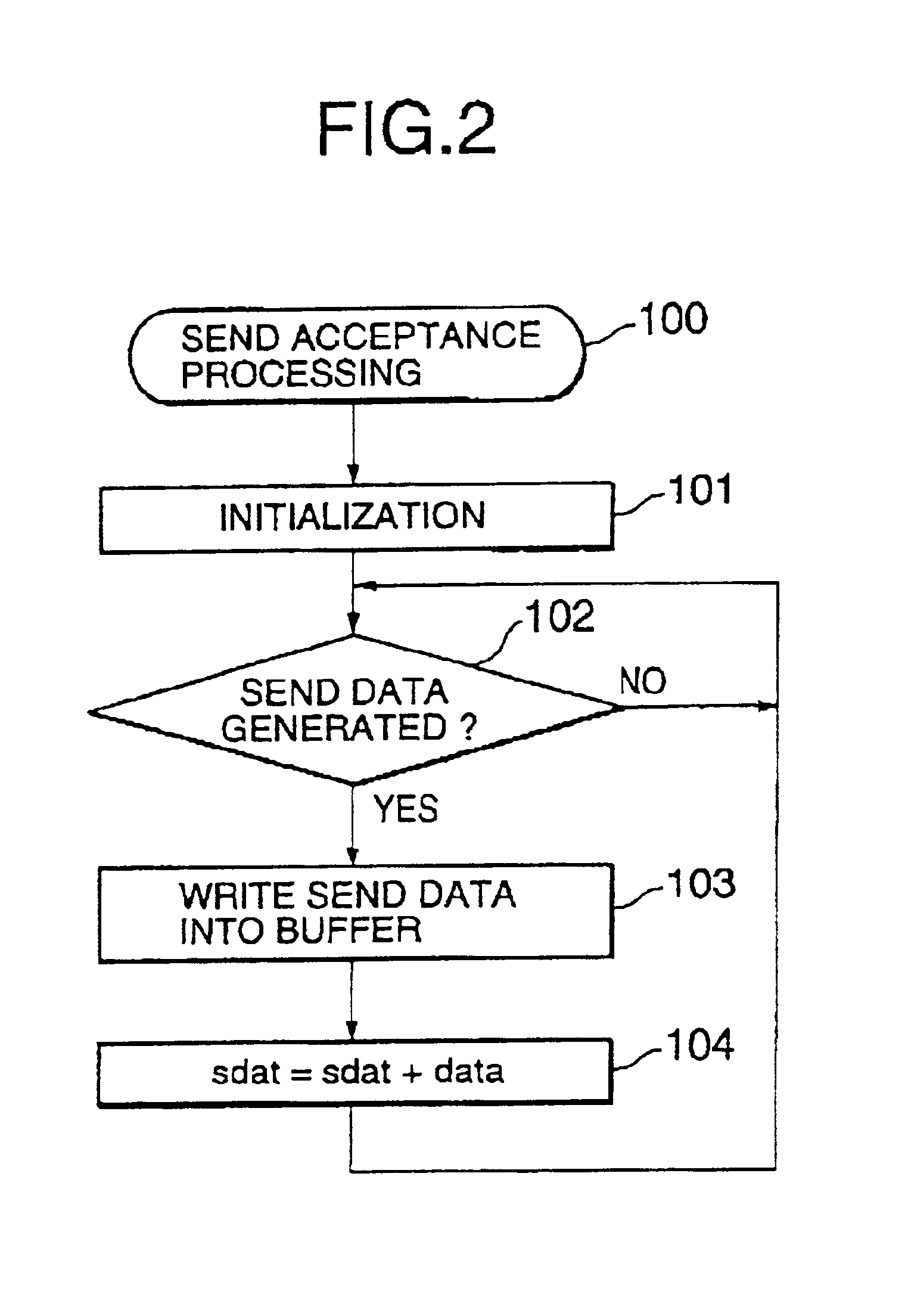
[0029]In operation, send data is received from the outside of the processing blo...


PUM


Abstract

A packet size control method allowing reduction in the period of time during which transmission is in a blocked state is disclosed. The size of a packet to be sent is determined depending on a measured round trip time (RTT), a current bandwidth of the data link layer, and a current congestion window size. First, a maximum segment size (MSS) is obtained based on the measured RTT and the current bandwidth of the data link layer using a table obtained by data transfer simulation. Thereafter, the obtained MSS is corrected using the current congestion window size. And the correct MSS is used to determine the final segment of data to be sent.

Description

BACKGROUND OF THE INVENTION[0001]1. Field of the Invention[0002]The present invention relates to a packet size control method and apparatus in a packet transfer system.[0003]2. Description of the Related Art[0004]In data transmission through a network having a relatively large transfer delay, there has been known a problem such that the sending processing is blocked during a time period from transmission of a send window of data until reception of an acknowledgment (ACK) from a receiving side in the case where the product of bandwidth (or transfer rate) and round trip time (RTT) that is a delay time required for data round trip is greater than the size of a send window. This makes it difficult to use available network bandwidth effectively and enable data transfer with efficient throughput.[0005]One of conventional techniques to solve this problem has been disclosed in Japanese Patent Application Unexamined Publication No. 09-247209. This prior art offers a system in which the trans...

Claims


Application Information

Patent Timeline
Patent Type & Authority Patents(United States)
IPC IPC(8): H04L1/00H04L12/28H04L47/27H04L47/36H04L47/43
CPCH04L1/0007
Inventor ONO, YOSHIHIRO
Owner NEC CORP
Why Eureka
Try Eureka