
Method and apparatus for converting data packets between a higher bandwidth network and a lower bandwidth network

a technology of data packets and networks, applied in transmission, time-division multiplexing selection, electric/magnetic signal storage, etc., can solve the problems of significant limitations on the physical distance that the network can cover, and achieve the effect of efficient communication of data packets

Active Publication Date: 2005-08-23
ECE TELECOM LTD
View PDF25 Cites 27 Cited by
  • Summary
  • Abstract
  • Description
  • Claims
  • Application Information

AI Technical Summary

Benefits of technology

The present invention provides an apparatus and method for efficiently communicating a data packet for a larger bandwidth network across a smaller bandwidth network. The apparatus and method can convert a conventional data packet received from a first broadband network to a conventional data packet suitable for transmitting on a second broadband network, with no loss of data content. This conversion can be done by removing idle bytes from the data stream, framing the packets in accordance with a conventional protocol, and providing the framed data packets to the payload network. The apparatus and method can be adapted to any OCnc (n=1, 3, 12) payload network and can absorb traffic bursts using a large buffer. The invention allows for the restoration of the data packet to a format compatible with the first broadband network at the terminal end of the SONET / WAN.

Problems solved by technology

A main drawback with conventional Ethernet is that there are significant limitations on the physical distance that the network can cover.

Method used


Image

  • Method and apparatus for converting data packets between a higher bandwidth network and a lower bandwidth network
  • Method and apparatus for converting data packets between a higher bandwidth network and a lower bandwidth network
  • Method and apparatus for converting data packets between a higher bandwidth network and a lower bandwidth network

Examples


Embodiment Construction

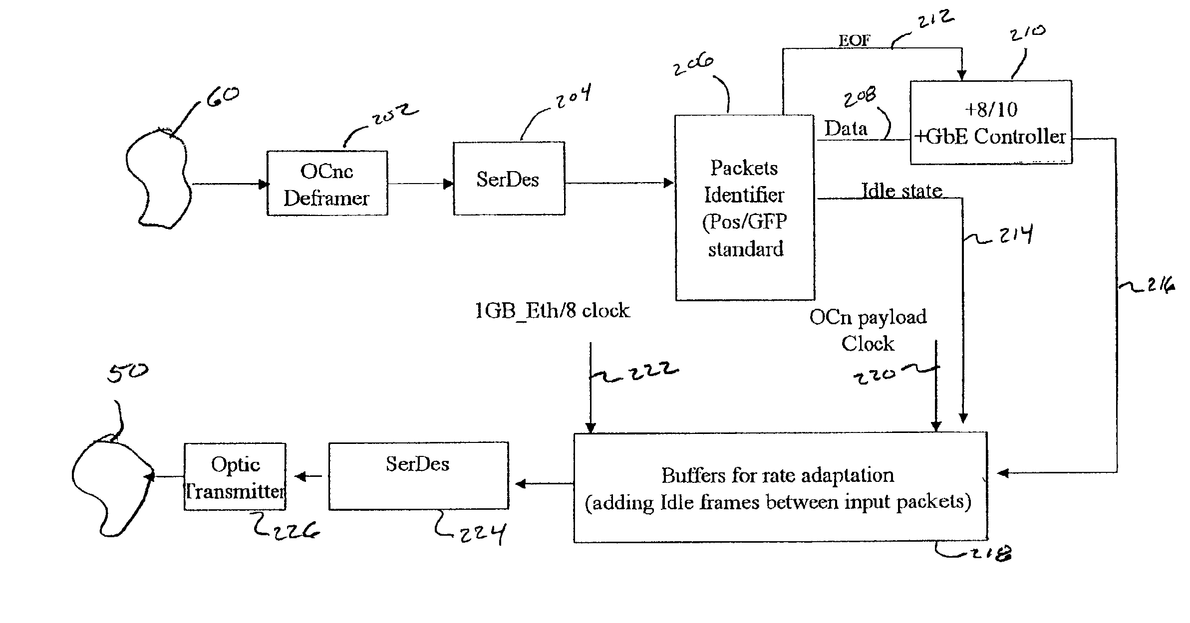
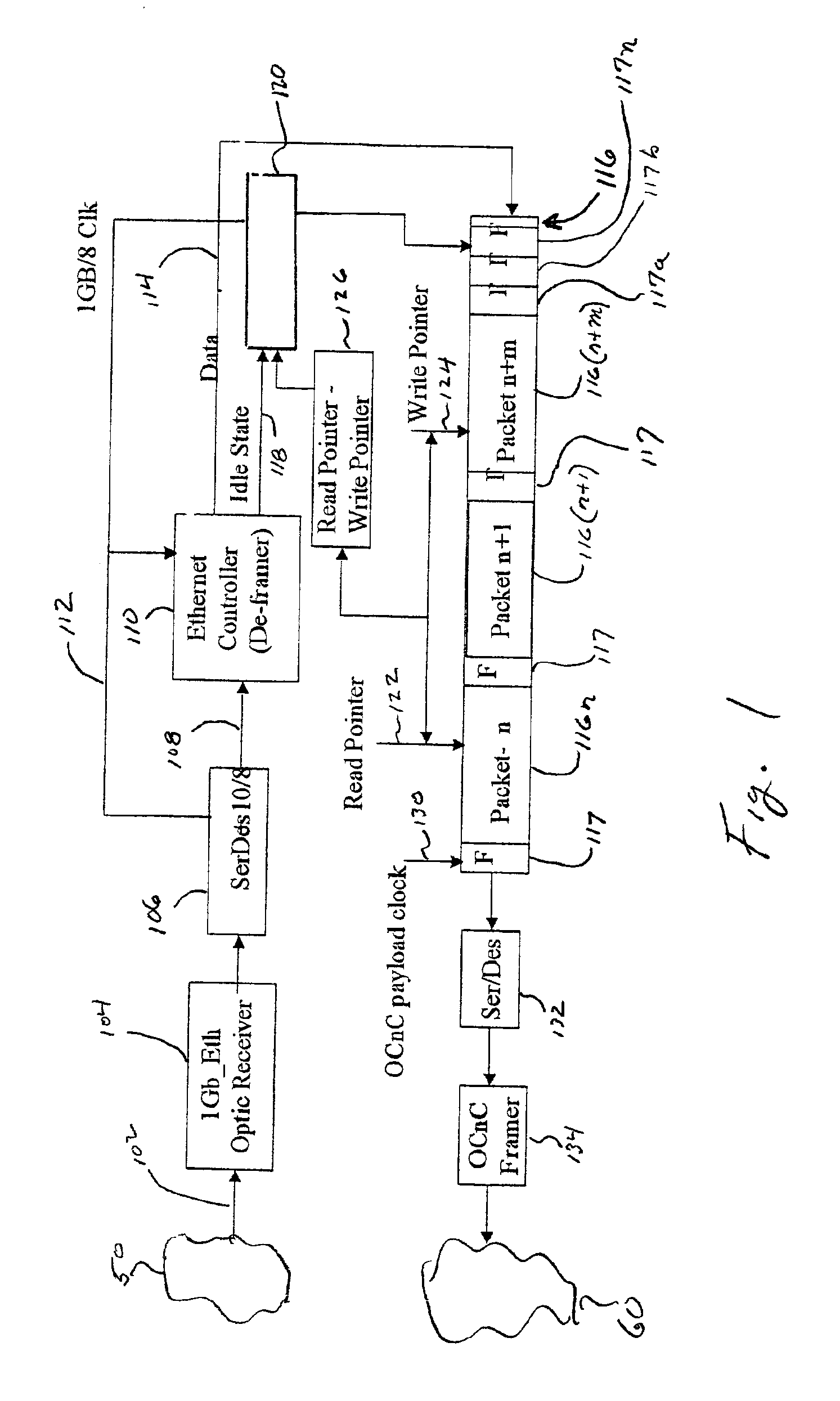
[0036]With reference to the figures in which like numerals represent like elements or components throughout the several views, and in particular with reference to FIG. 1, there is shown a schematic block diagram of an embodiment of an apparatus according to the present invention. The apparatus is for converting a bursty sequence of conventional 1 Gb Ethernet data packets (not shown) of a 1 Gb Ethernet network, schematically shown at 50, to a conventional OC12 data packet (not shown) of an OC12 payload network, schematically shown at 60.

[0037]An Ethernet optical fiber 102 is connected at one end to Ethernet network 50. Another end of Ethernet optical fiber 102 is or connected to an input of a conventional 1 Gb Ethernet optical receiver 104. An output of optical receiver 104 is connected to an input of a conventional serializer-deserializer 106. A first output of serializer-deserializer 106 is connected by a link 108 to an input of a conventional Ethernet Controller or Deframer 110. A...


PUM


Abstract

A method and apparatus for converting bursty, packetized data traffic from a wide bandwidth network to a constant, average rate traffic on a payload network having a narrower bandwidth is disclosed. The method includes converting a packet burst received from the wide bandwidth network to a serial stream having first and second pluralities of bytes, the second plurality of bytes having only idle bytes; substituting a place keeping flag for said second plurality of bytes thereby providing a reduced data; encapsulating the reduced data in a second packet; and providing the second packet to the narrower bandwidth network at a constant, average traffic rate. The method also includes converting the second packet received from the narrower bandwidth network to a second serial stream; substituting a plurality of idle bytes for the place keeping flags; converting the second serial stream and substituted idle bytes to a third packet; and providing the third packet to the wide bandwidth network.

Description

RELATED APPLICATION[0001]This application is related to an application entitled Method and Apparatus for Converting Data Packets between a Higher Bandwidth Network and a Lower Bandwidth Network Having Multiple Channels by the same inventor and filed the same day as this application, said application being incorporated in its entirety herein by reference.FIELD OF THE INVENTION[0002]This invention relates, in general, to a method and apparatus for converting a data packet for transmission and reception in a communication network, and in particular to a method and apparatus for converting a data packet received from a first broadband telecommunications network to a second data packet configured for transmission on a payload network having a narrower bandwidth than the first broadband network; and, after transmission on the payload network, reconverting the second data packet back to a format of the first broadband network. In a particular embodiment, this invention relates to a method ...

Claims


Application Information

Patent Timeline
Patent Type & Authority Patents(United States)
IPC IPC(8): H04J3/16H04L25/05H04L25/02H04L7/04H04Q11/04
CPCH04J3/1617H04L25/05H04J2203/0085H04L2007/045
Inventor JORDAN, REUVEN D.
Owner ECE TELECOM LTD
Learn More