Method and apparatus for determining characteristics of components of a communication channel

a technology of communication channel and component, applied in the direction of electrical equipment, radio transmission, transmission monitoring, etc., can solve the problems of increasing the difficulty of identifying slots, creating interference to payload signals of operational satellites, and reducing the efficiency of communication channels, so as to avoid interference of adjacent signals and simplify intersystem coordination

Inactive Publication Date: 2005-08-23
SES ASTRA SA
View PDF8 Cites 39 Cited by
  • Summary
  • Abstract
  • Description
  • Claims
  • Application Information

AI Technical Summary

Benefits of technology

[0021]It is an object of the invention to simplify the intersystem coordination in a beginning of life test and to avoid the interference of adjacent satellite systems.

Problems solved by technology

As each of said high power amplifiers is normally operated in its saturation point, multiple signals would create intermodulation products and distortion of the signals.
The reason for this is for instance that if the satellite contains transponders (backup) which may interfere with operational transponders, the measurement signal on the satellite under test may create interference to payload signals of the operational satellites.
However, as the geostationary arc is more and more crowded with Ku-band satellites, it becomes more and more difficult to identify a slot, in which all bands of the satellite under test may be measured with high power signals.
(1) The presence of other maritime satellites resulted in non-permissible frequency slots in which it was not allowed to generate a carrier from the ground or from the satellite is payload, e.g. the TDMA access channel and the search and rescue frequency band. This was accommodated in the software of the in-orbit testing computer by creating a frequency plan which inhibited use of the non-permissible frequency slots, such that test signals can only be generated in the permitted frequency channels.
(2) The second problem was created by the forward transponder containing an automatic level control function which keeps the output power constant irrespective of the transponder loading. The consequence is that the transmitted noise power increases, as transponder loading decreases, to reach an unacceptable level (from the interference point of view) when the transponder is not loaded. This difficulty has been overcome by ensuring a permanent minimum loading of the forward transponder. The loading was created by automatically up-linking two carriers, generated by dedicated synthesizers, during the inactive periods of the payload commissioning and acceptance phases. In the case of a malfunction in the C-band up-link during any in-orbit test, the minimum loading violation was detected by a specific computer program activating the loading carriers and aborting the ongoing test. The last result was for the European Space Operations Center to switch off the satellite payload.
As in a channel using a high power amplifier like a TWTA, the amplitude to phase modulation (AM / PM) conversion can lead to erroneous measurements, the power of the MLA signal has to be far below the saturation point.
U.S. Pat. No. 5,546,421 identifies the problem that the impedance presented by the bi-directional signal path to the hybrid may change dynamically during operation.
The most important drawback of the conventional testing techniques is that the measurement signal can create interference to an adjacent satellite system.
On the other hand, the measurement signal itself is subject to noise and interference created by signals coming from adjacent satellites.

Method used


Image

  • Method and apparatus for determining characteristics of components of a communication channel
  • Method and apparatus for determining characteristics of components of a communication channel
  • Method and apparatus for determining characteristics of components of a communication channel

Examples


Embodiment Construction

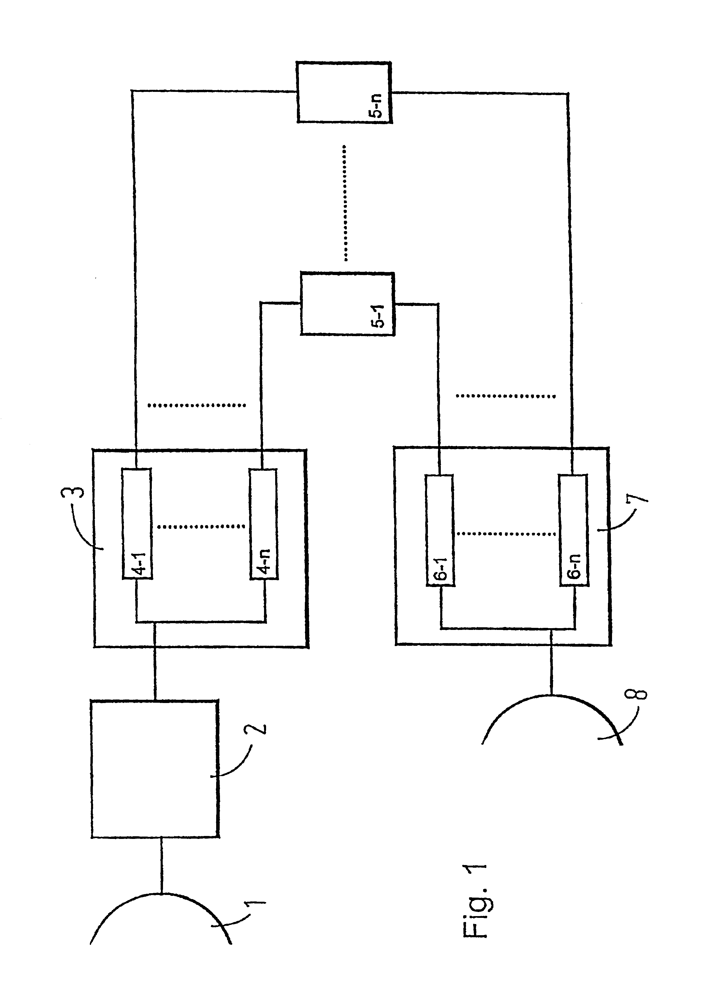
[0139]For the purpose of describing an embodiment of the invention, FIG. 1 shows the components of a transponder in a communication satellite as an example for a communication channel which was already explained above.

[0140]Since the filters provided in the input demultiplexer (IMUX) 3 and the output multiplexer (OMUX) 7 have a strong influence on the performance of the transponder, the method according to the invention will be explained in following with respect to measuring two specific characteristics, namely amplitude response and group delay, of these components of the transponder communication channels, the method of the invention being especially suitable for this application.

[0141]However, the same or other characteristics of other components of the communication channel can be determined by means of the method and the apparatus according to the invention.

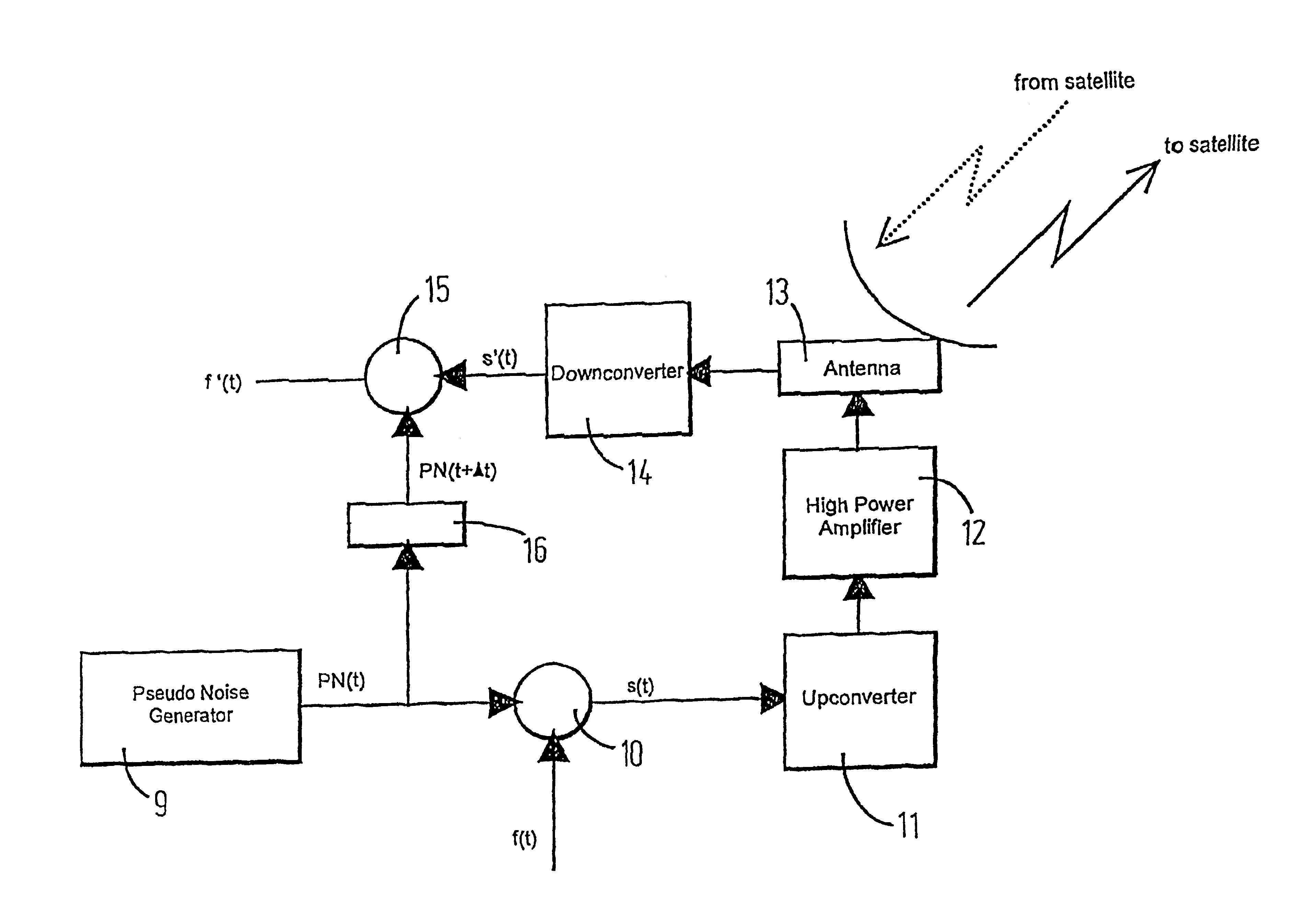
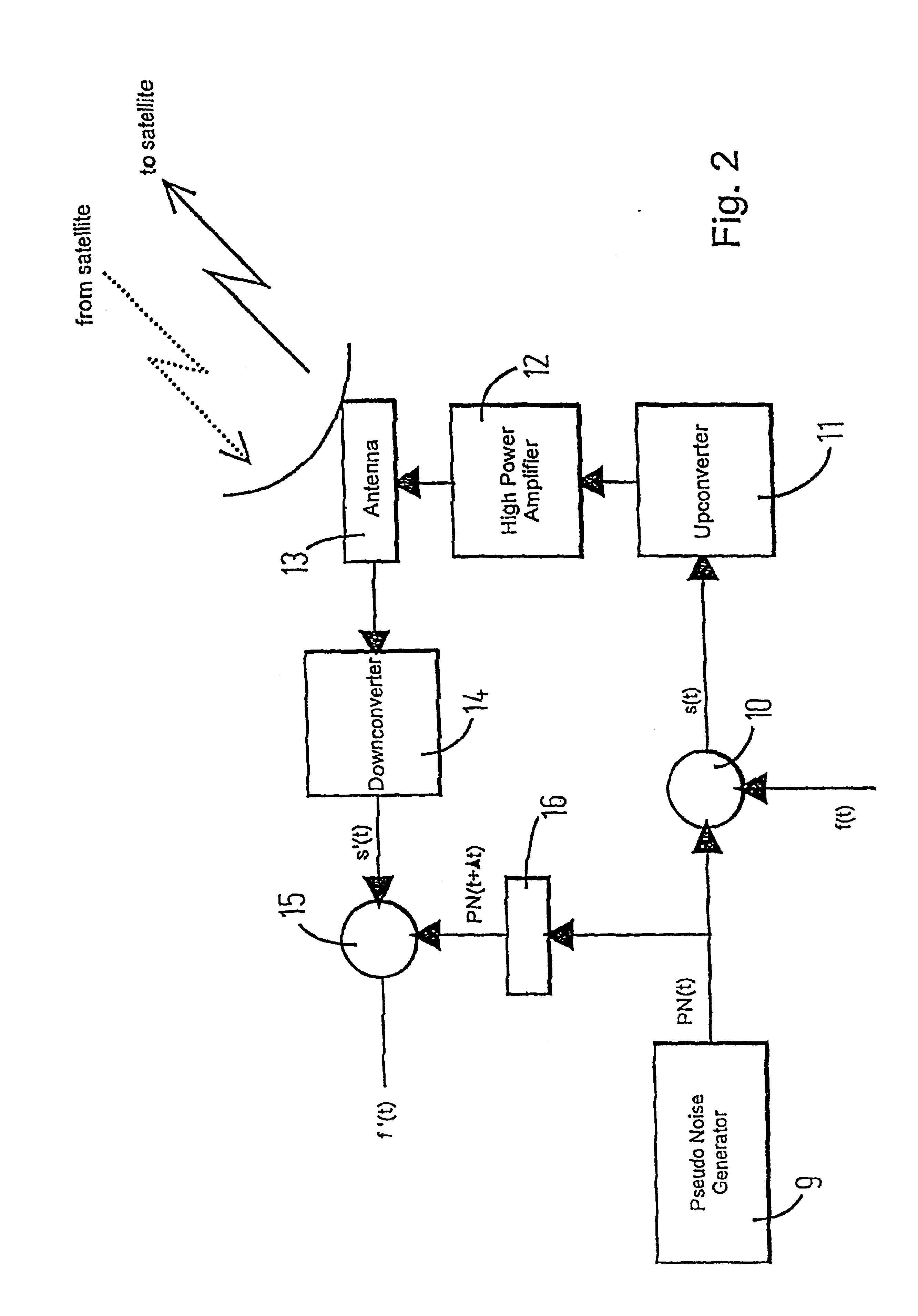
[0142]According to the invention, in a ground station as shown in FIG. 2, a pseudo noise signal PN(t) is generated by mea...


PUM


Abstract

The invention refers to a method and an apparatus for determining characteristics of components of a communication channel. In order to simplify the intersystem coordination in a beginning of life test of a satellite communication channel and avoiding the interference of adjacent satellite systems the method according to the invention comprises the following steps: modulating a clean carrier signal f(t) by spread spectrum modulation to generate a spreaded clean carrier signal s(t); transmitting said spreaded clean carrier signal s(t) through said communication channel at a first predetermined level; receiving a receive signal s′(t) corresponding to said spreaded clean carrier signal s(t) after having traveled through said communication channel; demodulating said receive signal s′(t) by spread spectrum demodulation to generate a despreaded carrier signal f′(t); determining characteristics of components of the communication channel on the basis of a comparison of said clean carrier signal f(t) and said despreaded carrier signal f′(t).

Description

CROSS REFERENCE TO RELATED APPLICATION[0001]This application is a Continuation of prior application No: PCT / EP99 / 04241 filed on Jun. 18, 1999, entitled Method and Apparatus for Determining Characteristics of Components of a Communication Channel, and now pending.FIELD OF THE INVENTION[0002]This invention refers to a method for determining characteristics of components of a communication channel and in particular of a satellite communication channel.BACKGROUND OF THE INVENTION[0003]After a successful launch of a new communications satellite, it is essential to test the communication's subsystem while a spacecraft is in orbit so as to compare with prelaunch data in order to ensure that no impairment has resulted from the stress of the launch and to verify that the spacecraft payload is compliant with the specification sought.[0004]As to the in-orbit test technology it has to be considered that the spacecraft has to be operational very quickly while not sacrifying the number of tests t...

Claims


Application Information

Patent Timeline
Patent Type & Authority Patents(United States)
IPC IPC(8): H04B17/00H04B7/185H04B1/707H04B1/7103H04B7/216
CPCH04B7/18519H04B17/0082H04B17/309
Inventor HARLES, GUYBETHSCHEIDER, GERHARD
Owner SES ASTRA SA
Why Eureka
Try Eureka