
Multi stage control architecture for error suppression in micromachined gyroscopes

a micro-machined gyroscope and control architecture technology, applied in the field of mems gyros, can solve the problems of large attitude errors, degradation of gyroscope performance, and no mems based gyroscope on the market capable of navigation grade, so as to reduce the time and cost of sensor calibration, eliminate large structural imperfections, and eliminate small perturbations

Inactive Publication Date: 2005-08-23
RGT UNIV OF CALIFORNIA
View PDF1 Cites 28 Cited by
  • Summary
  • Abstract
  • Description
  • Claims
  • Application Information

AI Technical Summary

Benefits of technology

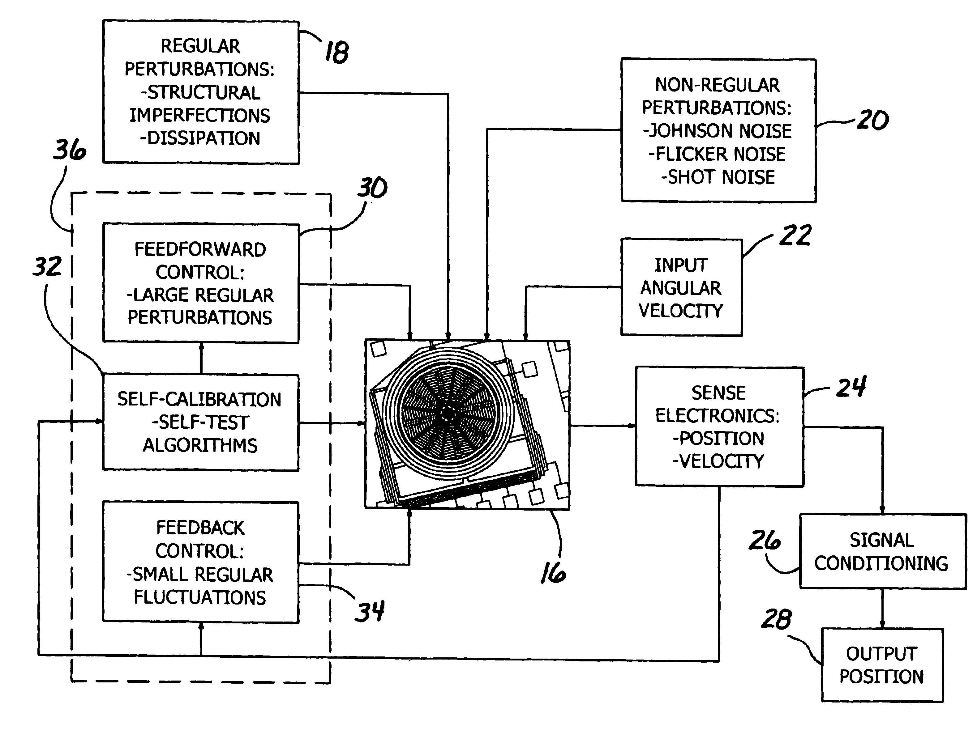
[0006]The invention is a multi stage architecture that integrates self-calibrative capabilities for identication of errors, active electronic “trimming” in the form of a feedforward control for elimination of large structural imperfections, and feedback control for elimination of smaller perturbations. Such a control architecture signicantly reduces the time and cost for sensor calibration and potentially improves long term performance by allowing for rapid in-run diagnostics.
[0010]The step of eliminating small errors and in-run perturbations in the gyroscope comprises the step of using electrostatic parallel plates to apply a feedback error suppression signal to the gyroscope.

Problems solved by technology

Currently, there are no MEMS based gyroscopes on the market capable of navigation grade inertial sensing, mainly due to inadequate drift and noise performance that result in large attitude errors upon integration of rate signals to obtain orientation.
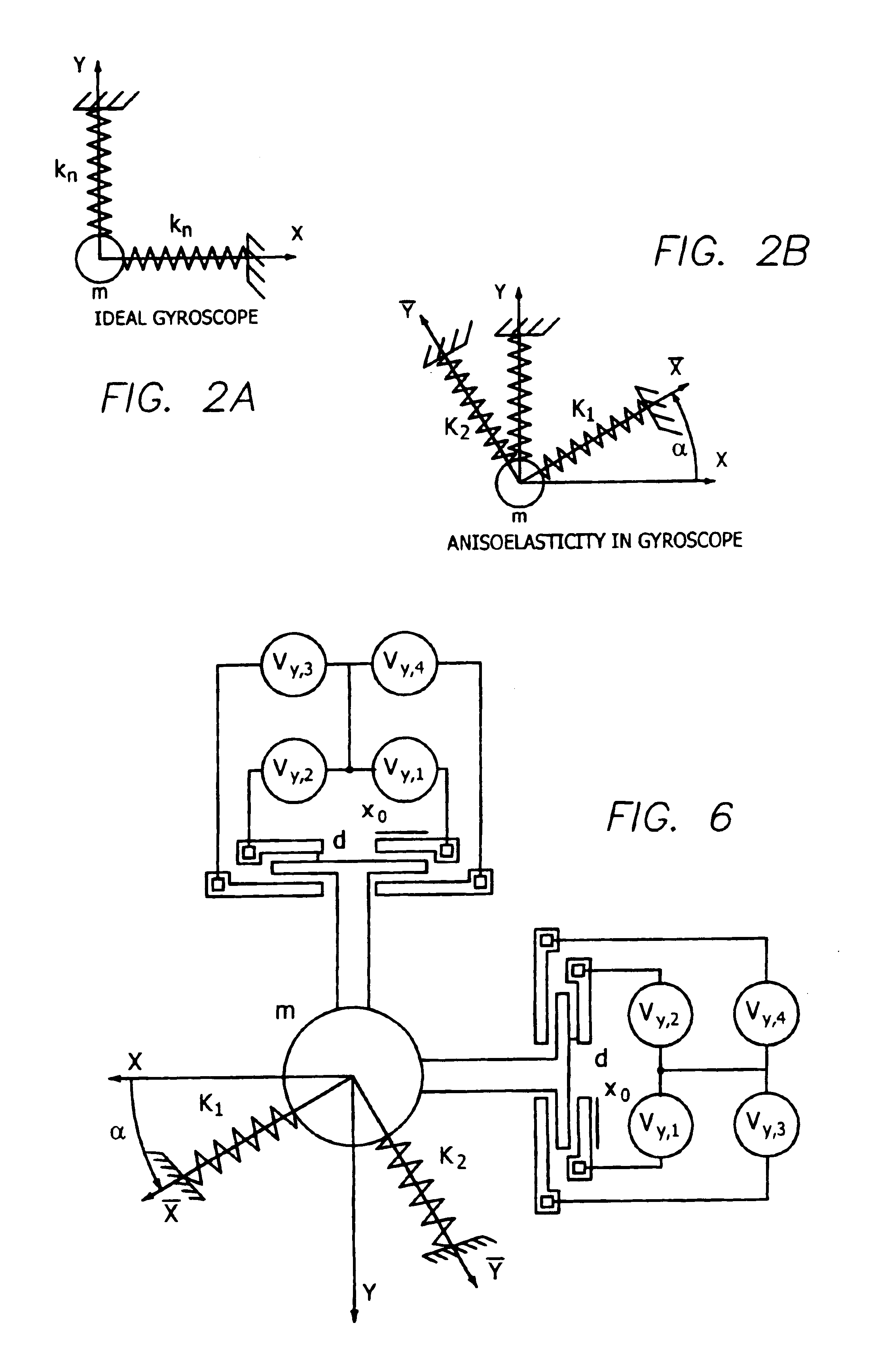
One of the contributing factors to this degradation in gyroscope performance is structural imperfections as a result of tolerance errors in the fabrication of the device.
However, as will be illustrated in this disclosure, when imperfections are large compared to the measured Coriolis force, compensation cannot be achieved with a purely feedback control without interfering with the Coriolis measurements.
These interferences cause scale factor and drift errors in the gyroscope, resulting in degraded performance.
The disadvantage is that this type of post processing is done exclusively by the manufacturer, usually under ideal laboratory conditions.
As a result, the end-user is still required to calibrate the device prior to use and then once the device is in use in the end-user's application, typically no additional calibration is possible.

Method used


Image

  • Multi stage control architecture for error suppression in micromachined gyroscopes
  • Multi stage control architecture for error suppression in micromachined gyroscopes
  • Multi stage control architecture for error suppression in micromachined gyroscopes

Examples


Embodiment Construction

Gyroscope Principles

[0039]All micromachined gyroscopes are vibratory in nature, measuring either angular rates by detecting energy coupled between orthogonal vibration modes due to Coriolis force or angle of rotation through the precession of an oscillation pattern. In a rate gyroscope, a structural element is forced into oscillation in one principle structural mode, designated the “drive” mode. The presence of rotation induced Coriolis force couples the sustained oscillation into an orthogonal structural mode, designated the “sense” mode. The magnitude of vibration induced in the sense mode is proportional to the rotation rate of the device.

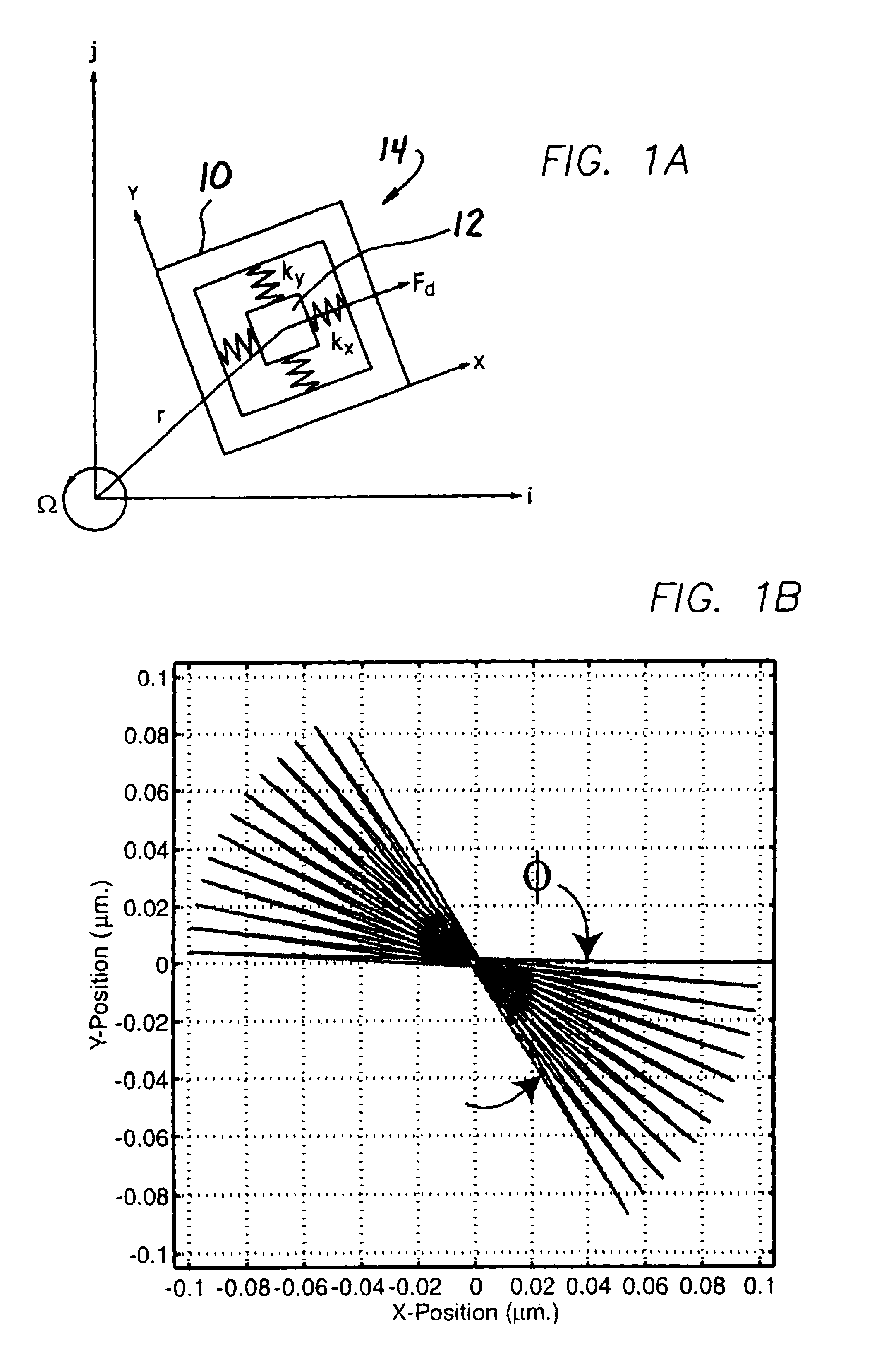
[0040]In a rate integrating gyroscope, the structural element is sustained in free oscillation and the presence of Coriolis force causes precession of the oscillation pattern, which is proportional to the angle of rotation of the gyro. As an illustration, consider a structural mass 12 attached to a frame 10 free to move in inertial space (i,j) a...


PUM


Abstract

Due to restrictive tolerancing, structural imperfections that reduce performance of fabricated micro gyroscopes are typical. While feedback control is normally used to compensate for these imperfections, there are limitations to how large of errors for which this strategy can compensate without interfering with the performance of the sensor. A multi stage control architecture comprising in situ self-diagnostic capabilities, electronic “trimming” of errors, and feedback control allows for the compensation of all magnitudes of errors without interfering with the performance of the device. The self-diagnostic capabilities include an algorithm for determining structural imperfections based on the dynamic response of the system. The feedforward portion of the control is used to “trim” large imperfections, while the feedback portion compensates for the remaining non-idealities and small perturbations. A control architecture is shown in a gyroscope using nonlinear electrostatic parallel plate actuation.

Description

BACKGROUND OF THE INVENTION[0001]1. Field of the Invention[0002]The invention relates to MEMs gyros and in particular to a method of suppressing errors.[0003]2. Description of the Prior Art[0004]As MEMS inertial sensors have begun to proliferate more into rate and tactical grade application markets, the current demand is for inertial sensors with higher precision and long term performance. Currently, there are no MEMS based gyroscopes on the market capable of navigation grade inertial sensing, mainly due to inadequate drift and noise performance that result in large attitude errors upon integration of rate signals to obtain orientation. One of the contributing factors to this degradation in gyroscope performance is structural imperfections as a result of tolerance errors in the fabrication of the device. As all MEMS devices are built using photolithographic processes, the relative tolerances are on the order of 10% or more. Currently, in order to operate with the highest precision, ...

Claims


Application Information

Patent Timeline
IPC IPC(8): G01C17/38G01C17/00G06F15/00G01C19/56G01C25/00
CPCG01C19/56G01C25/005G01C19/574
Inventor PAINTER, CHRISTOPHER C.SHKEL, ANDREI M.
Owner RGT UNIV OF CALIFORNIA
Learn More