Method of and apparatus for forming discharge tubes of low-pressure discharge lamps

a discharge tube and low-pressure discharge technology, which is applied in the manufacture of electric discharge tubes/lamps, glass tempering apparatuses, electrode systems, etc., can solve the problem of curvature radius limitation of the method, and achieve the effect of easy formation

Inactive Publication Date: 2005-08-30
GENERAL ELECTRIC CO
View PDF11 Cites 12 Cited by
  • Summary
  • Abstract
  • Description
  • Claims
  • Application Information

AI Technical Summary

Benefits of technology

[0009]The suggested method is particularly advantageous for the forming of discharge tubes with varying radius or direction of curvature. Due to the fact that the bending moment on the softened bending section is effected with the re-solidified second bending section, no central molding core is necessary, and coils with various diameters along the coil axis may be manufactured in large series. Further, not only coils, but many

Problems solved by technology

Further, not only coils, but many other shapes may be produced, the only limitatio

Method used


Image

  • Method of and apparatus for forming discharge tubes of low-pressure discharge lamps
  • Method of and apparatus for forming discharge tubes of low-pressure discharge lamps
  • Method of and apparatus for forming discharge tubes of low-pressure discharge lamps

Examples


Embodiment Construction

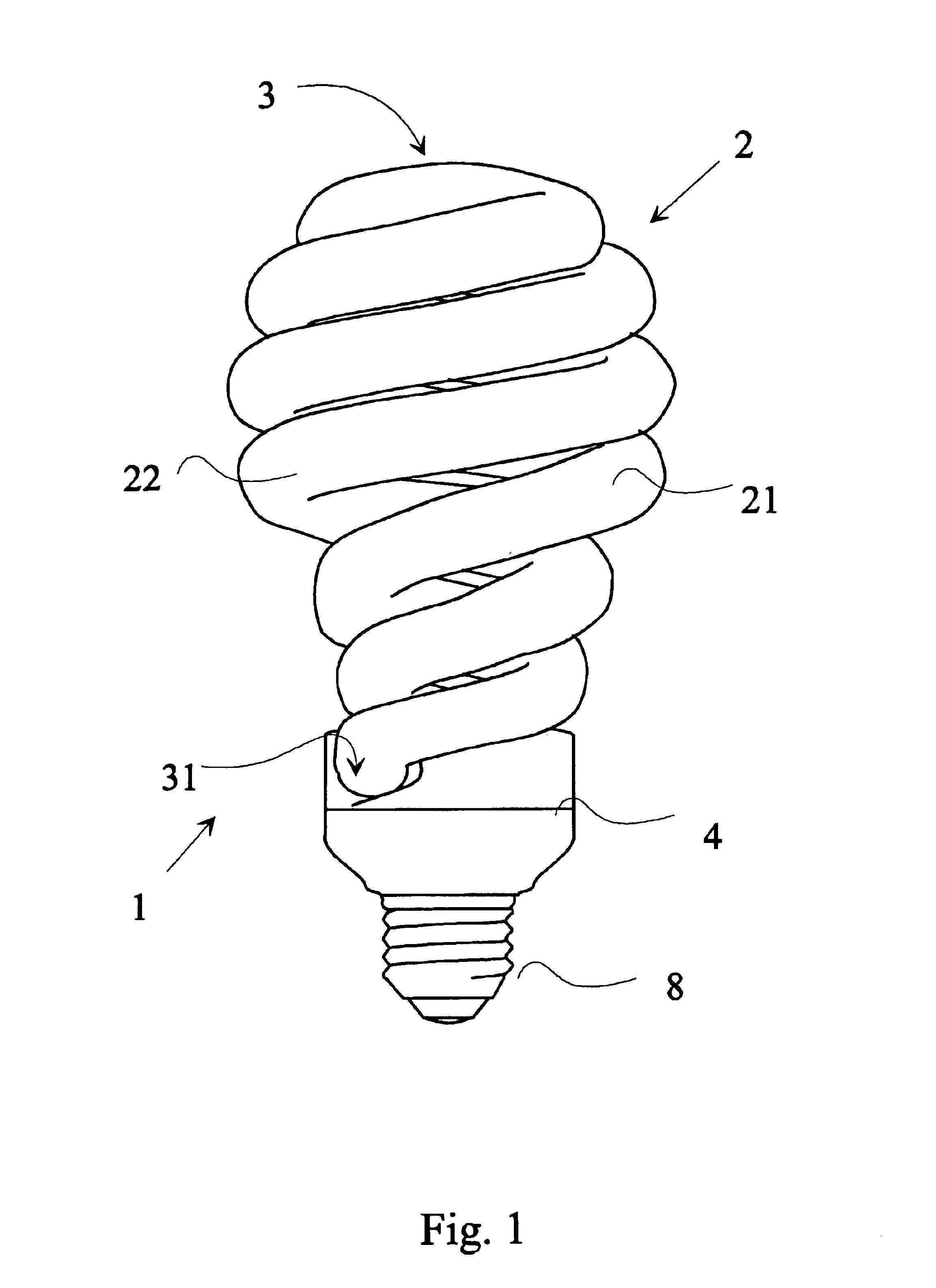
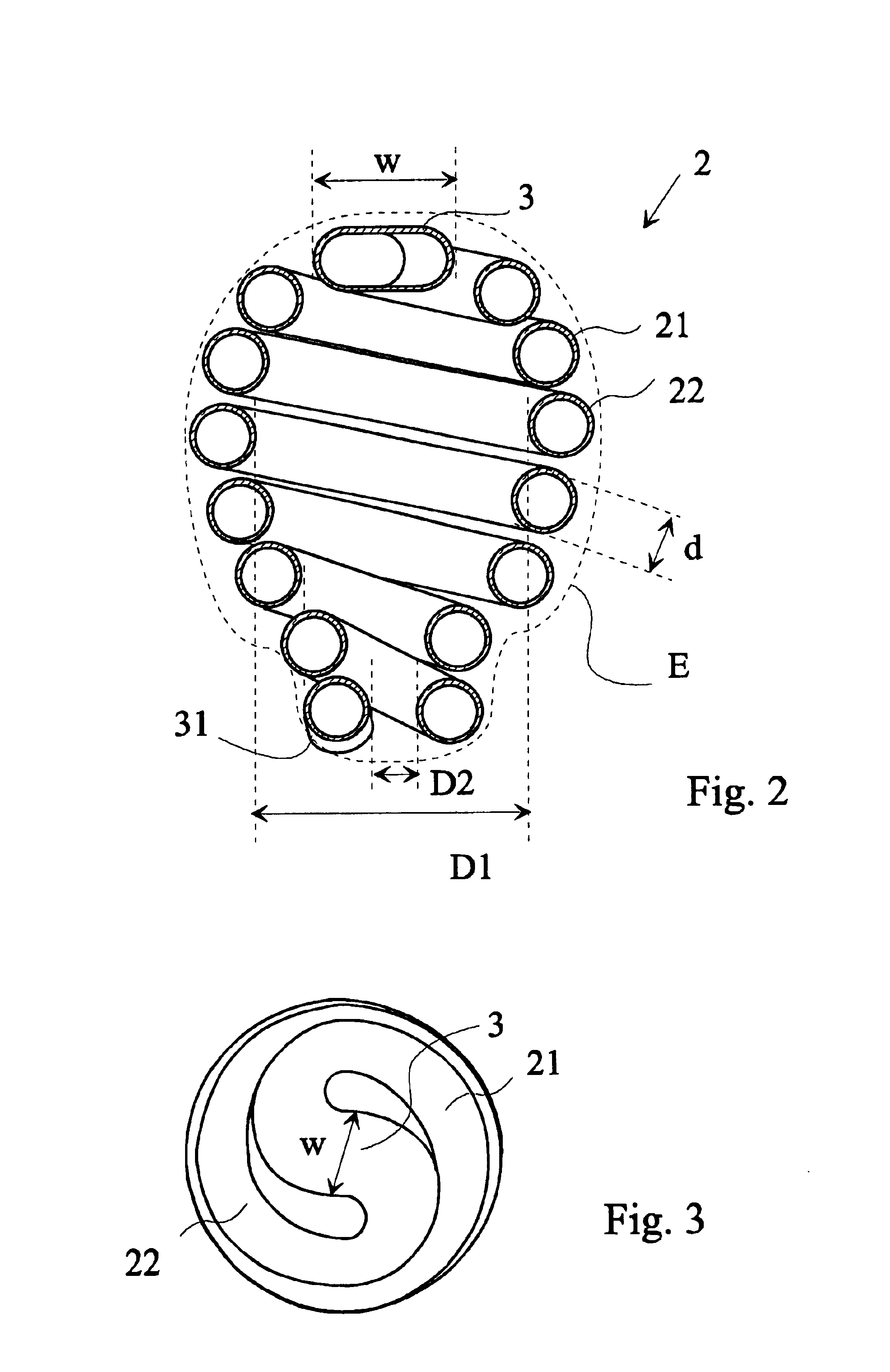
[0037]Referring now to FIGS. 1 to 3, there is shown a low pressure arc discharge lamp 1. The lamp 1 has a discharge tube 2, the ends 31 of which are inserted into a lamp housing 4 or base terminal. The lamp 1 of FIG. 1 has two spiral shaped discharge tube portions 21 and 22 which are interconnected through a cold chamber portion 3 at the upper ends of the tube portions 21 and 22 in order to form a double helix.

[0038]The discharge tube 2 is mechanically supported by the lamp housing 4. The lamp housing 4 surrounds the ends 31 of the discharge tube 2. More precisely, the sealed ends 31 of the tube portions 21,22 are within the lamp housing 4, while the major part of the tube portions 21,22 is external to the lamp housing 4. The lamp 1 is of a type where light is emitted by a phosphor layer deposited on the inner surface of the discharge tube 2. Such a discharge lamp arrangement is known by itself. In a typical embodiment, the lamp housing 4 is equipped with a screw terminal 8, which f...


PUM

PropertyMeasurementUnit
Temperatureaaaaaaaaaa
Lengthaaaaaaaaaa
Diameteraaaaaaaaaa

Abstract

There is disclosed a method for forming a discharge tube for a low-pressure discharge lamp. In the method, an end of a section of the discharge tube is fastened with first clamping means, and a second end of the section in held in an oriented position. The section is heated to a softening temperature, and a bending moment is exerted on the section between the first end and the second end for achieving the desired radius or direction of curvature of the section. The holding of the second end of the section and the exertion of the bending moment on the section are effected at least partly with another re-solidified section of the discharge tube which is adjacent to the softened first section. An apparatus for performing the method is also disclosed. The apparatus comprises first and second clamping means for positioning the ends of a bending section of the discharge tube in an oriented position relative to each other, and for exerting a bending moment on the ends. The second clamping means is also used for positioning the ends of a starting bending section relative to each other. Heating means are provided for heating the bending section to a softening temperature, and controllable support means for positioning the first and second clamping means. Control means are used for synchronizing the operation of the controllable support means. The first and second clamping means and the heating means are suitable for achieving a desired radius or direction of curvature of the bending sections heated to the softening temperature.

Description

FIELD OF THE INVENTION[0001]The invention relates to a method of forming a discharge tube for a low-pressure discharge lamp in which the discharge tube has at least one curved section. The invention also relates to an apparatus for implementing the method and for forming a discharge tube for a low-pressure discharge lamp.BACKGROUND OF THE INVENTION[0002]Low pressure discharge lamps are well known in the art. These lamps contain small doses of mercury which radiates under the influence of the discharge arc. In order to achieve maximum light output, it is desirable to make the discharge tube of the lamp as long as possible. In order to achieve light outputs comparable to the light output of a traditional incandescent bulb, the application of discharge tubes with a length in excess of tens of centimeters is necessary. Such tubes must be folded into various forms, in order to make them compact enough for various lamp shades and covers, which were originally designed for incandescent bul...

Claims


Application Information

Patent Timeline
IPC IPC(8): C03B23/00C03B23/045C03B23/043C03B23/06H01J9/24H01J61/30
CPCC03B23/043C03B23/045C03B23/06H01J9/247H01J61/30
Inventor KERENYI, ISTVANCSAPO, JOZSEFTOKES, JOZSEF
Owner GENERAL ELECTRIC CO
Why Eureka
Try Eureka