
Method and apparatus for providing fluid transfer between a marine platform and a service vessel

Inactive Publication Date: 2005-08-30
WILLIAMSON JOHN P
View PDF5 Cites 11 Cited by
  • Summary
  • Abstract
  • Description
  • Claims
  • Application Information

AI Technical Summary

Benefits of technology

[0013]A feature of the present invention is that the truss does not provide a walkway that might become slippery if coated with leaking fluid.

Problems solved by technology

A very dangerous practice that has evolved is the placement of fluid transfer hoses on a personnel ramp that spans between a production platform and a work vessel.
Such a walkway can become wetted with leaking fluid that is being transferred via the hoses.
Many of these fluids are ver viscous and slippery.
A worker can easily slip and fall in such a hazardous situation.
Danger is compounded because the walkway can be at a lofty elevation if a jack up barge is servicing a fixed platform having a deck that is many feet above the water's surface.
Minerals Management Services or “MMS”) have regulations prohibiting such practices, workers forget the regulations during the performance of their jobs and subject themselves to injury or death.

Method used


Image

  • Method and apparatus for providing fluid transfer between a marine platform and a service vessel
  • Method and apparatus for providing fluid transfer between a marine platform and a service vessel
  • Method and apparatus for providing fluid transfer between a marine platform and a service vessel

Examples


Embodiment Construction

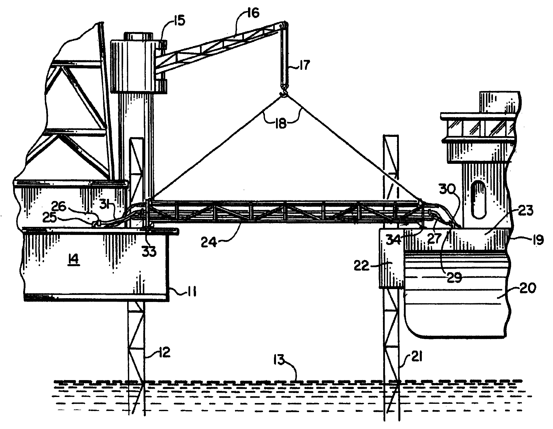
[0024]The present invention provides an improved method and apparatus for the transfer of fluids between a fixed marine platform 11 and a service vessel or work vessel 19 (see FIG. 5). In FIG. 5, the fixed production platform 11 can be a jack up type production rig, a permanently installed rigid platform mounted upon a jacket, or semi-submersible that is maintained in its position using very large buoys and anchors or a GPS, self propelled system.

[0025]The platform 11 can be supported upon legs 12 such as telescoping legs in the case of a jack up rig production platform or the legs 12 can be part of an overall structural jacket that supports a deck 14 at a position that is spaced above the water's surface 13. Such fixed platforms are known in the art and are used commonly in coastal or offshore waters for the production of oil and gas.

[0026]In FIG. 5, a lifting device 15 such as a crane can be provided on either the fixed marine production platform 11 or the service vessel 19 in the...


PUM

PropertyMeasurementUnit
Lengthaaaaaaaaaa
Flexibilityaaaaaaaaaa
Elevationaaaaaaaaaa

Abstract

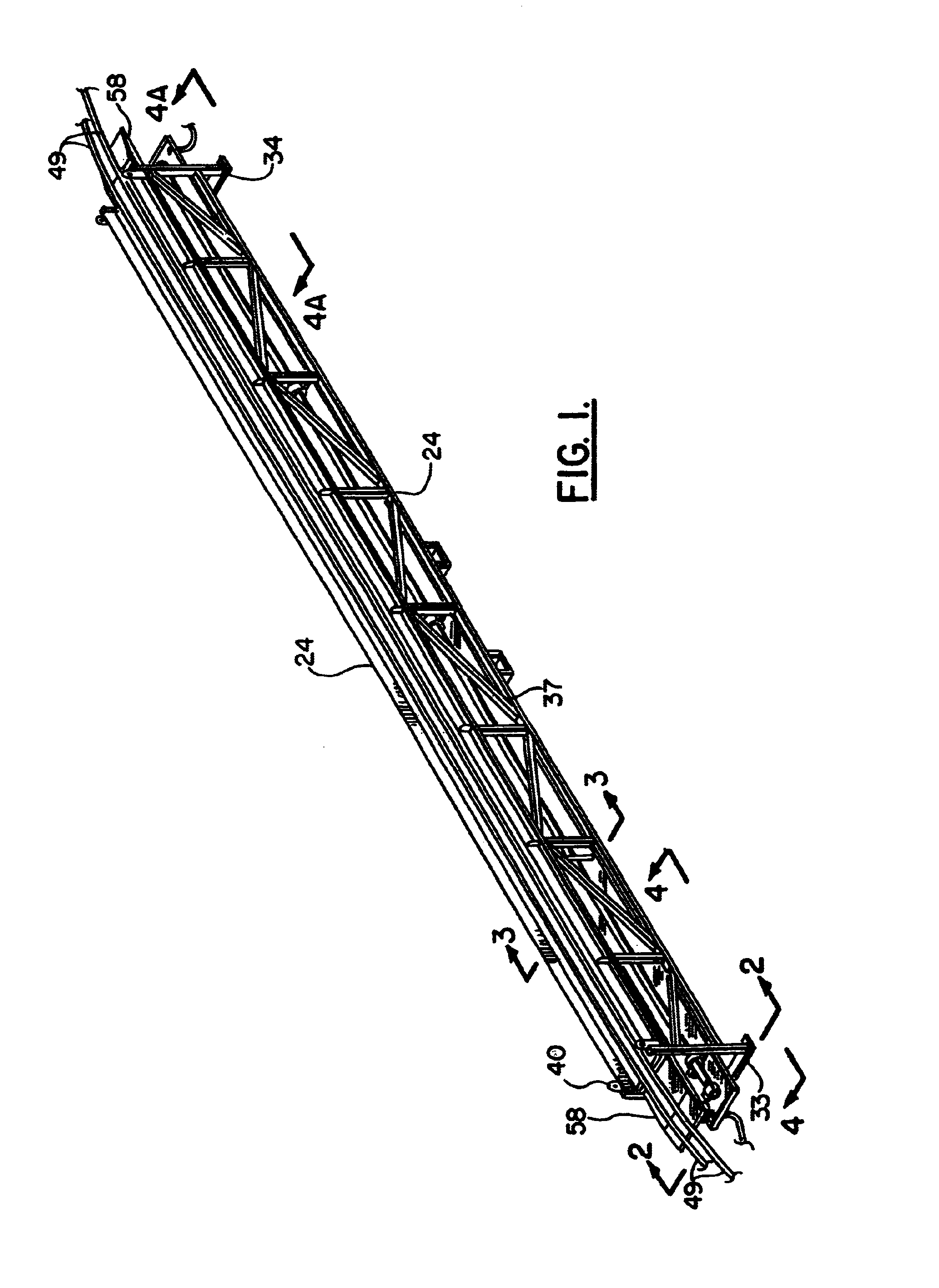
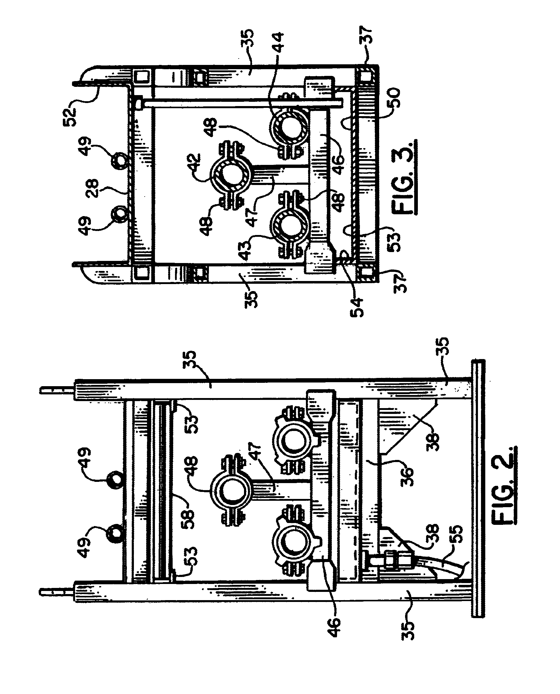
The present invention provides a method and apparatus for fluid transfer between a fixed marine production platform and a work vessel (eg. jack up barge). The method includes positioning the work vessel next to the production platform and then adjusting the elevational position of the vessel relative to the production platform so that the deck of the production platform and the deck of the work vessel or at about the same elevational position. A bridge truss spans between the deck portions of the production platform and work vessel, the truss having interconnected truss members and a planar surface that enables flexible hoses to be supported by the truss. The truss further includes a plurality of piping spool pieces that span across the truss. Ends of the spool pieces have quick connect fittings that enable the spool pieces to be quickly connected to the piping system of the production platform and work vessel. The gap between the production platform and the work vessel are spanned with the truss. Piping systems on the production platform and work vessel are connected to the spool pieces at the quick connect fittings so that fluid transfer is enabled between the production platform and the work vessel via the spool pieces on the truss. An upper tray enables flexible hoses (eq. hydraulic hoses) to span between the work vessel and production platform.

Description

CROSS-REFERENCE TO RELATED APPLICATIONS[0001]This is a continuation-in-part of U.S. Ser. No. 10 / 083,193, filed Feb. 26, 2002 now U.S. Pat. No. 6,609,544.STATEMENT REGARDING FEDERALLY SPONSORED RESEARCH OR DEVELOPMENT[0002]Not applicableREFERENCE TO A “MICROFICHE APPENDIX”[0003]Not applicableBACKGROUND OF THE INVENTION[0004]1. Field of the Invention[0005]The present invention relates to maintenance of a fixed, marine production platform, such as an oil and gas production platform. More particularly, the present invention relates to the maintenance of a fixed marine production platform wherein fluid transfer between a fixed marine production platform and a work vessel (eg. jack up barge) is accomplished by spanning the gap between the production platform and work vessel with a truss that is liftable and self supporting, the truss being equipped with multiple fluid transfer pipe spool pieces that have quick connect fittings for coupling to respective piping systems of the marine produc...

Claims


Application Information

Patent Timeline
IPC IPC(8): B63B27/00B63B27/24B63B27/34
CPCB63B27/24
Inventor WILLIAMSON, JOHN P.
Owner WILLIAMSON JOHN P
Learn More