Stabilizer device for rotary string of drill rods with reduced friction

a stabiliser device and rotary string technology, which is applied in the direction of drill bits, drilling accessories, earthwork drilling and mining, etc., can solve the problems of insufficient stability of the position, difficulty in perfect control of the displacement of the contact element of the stabiliser, and complete jamming of the drill string, so as to reduce the friction of the stabiliser

Inactive Publication Date: 2005-08-30
VAM DRILLING FRANCE
View PDF10 Cites 23 Cited by
  • Summary
  • Abstract
  • Description
  • Claims
  • Application Information

AI Technical Summary

Benefits of technology

[0038]In the case where the stabiliser has an external contact element mounted so as to rotate and to slide on the central body of the stabiliser, the axial retention of the contact element mounted so as to be movable in translation and in rotation on the central body of the stabiliser is ensured by two axially extending restoring devices such as restoring springs which are in contact at their axial ends at the same time with two radial edges of the central shaft and of the contact element which are compressed and exert on a first axial end and on a second axial end of the contact element opposing forces which make it possible to obtain a very great stability of position of the contact element in a configuration ensuring its rotatable mounting on the drill rod and its immobilisation in rotation in the

Problems solved by technology

This friction increases the forces brought into play along the drill string during drilling and, in certain cases, may become excessive or lead to complete jamming of the drill string.
In this case, when the contact element is displaced in one direction, one of the restoring springs is compressed and the other spring is relaxed, such that the force applied by one of the springs increases while the force applied by the other spring decreases, so that perfect management of the control of the displacement of the contact element of the stabiliser is difficult.
When the contact element of the stabiliser is engaged in a coupling position with the central shaft by one of its end parts, the stability of this position is not ensured because the restoring forces are not exerted in an identical manner on the two ends of the external contact element.
Such a device can only function correctly for moderate axial actuating forces.
In particular, such stabilisers with a friction clutch cannot be used as stabilisers having a very wide operating range in so far as the axial forces are concerned.
Furthermore, the mounting of the contact element of the stabiliser between two restoring springs in the devices according to the prior art also limits the extent of the operating range in the non-rotary m

Method used


Image

  • Stabilizer device for rotary string of drill rods with reduced friction
  • Stabilizer device for rotary string of drill rods with reduced friction
  • Stabilizer device for rotary string of drill rods with reduced friction

Examples


Embodiment Construction

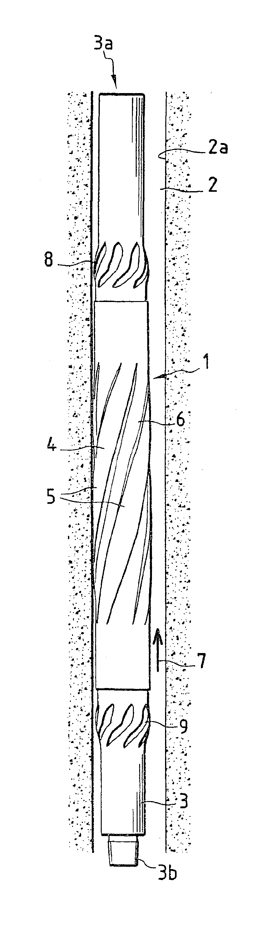
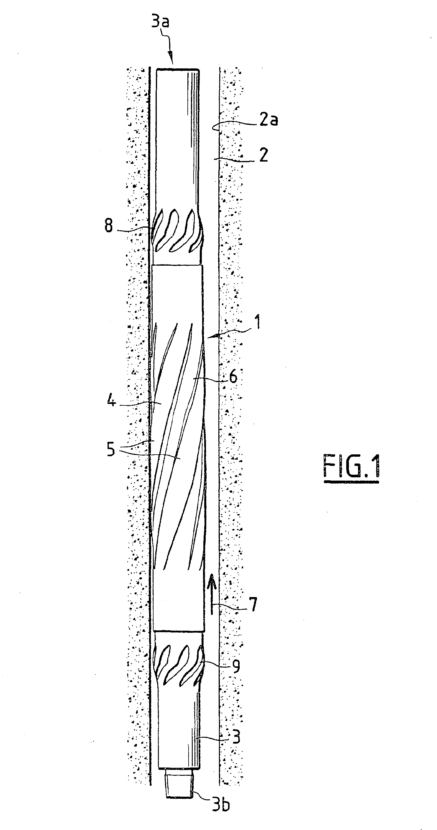
[0046]FIG. 1 shows a stabiliser according to the invention, designated overall by the reference numeral 1, in the operating position in the interior of a borehole 2 produced by a tool of a string of drill rods on which the stabiliser 1 is interposed which is intended to ensure the centring and the guiding of the drill string in the borehole before the drilling advances.

[0047]The stabiliser 1 has a central body 3 on which is mounted a tubular element 4 which constitutes the external casing for contact of the stabiliser with the wall 2a of the borehole 2.

[0048]The body 3 of the stabiliser has at a first axial end 3a, or upper end, and at a second axial end 3b, or lower end, respectively a female screw connection element and a male screw connection element.

[0049]The threaded connecting parts 3a and 3b of the stabiliser which are produced in the form of a tapped part and a threaded part in the shape of a truncated cone are conventional elements in the case of drilling equipment and perm...


PUM


Abstract

The stabilizer (1) has a tubular central body (3) having means for connection (3a, 3b) to a first and a second component of the string of drill rods and at least one external contact element (4) with a wall (2a) of the borehole (2). The external element (4) for contact of the stabilizer (1) with the wall (2a) of the borehole (2) has at least one means for activation (6) of a means (7) co-operating with the wall (2a) of the borehole (2) to limit the friction between the contact element (4) and the wall (2a) of the borehole (2). The activation means can consist of inter-blade spaces (6) for acceleration of the circulation (7) of the drilling liquid or by a means for coupling in rotation of the external element (4) and the central body (3) of the stabilizer (1).

Description

FIELD OF THE INVENTION[0001]The invention relates to a stabiliser device for a rotary string of drill rods with reduced friction.BACKGROUND OF THE INVENTION[0002]In order to carry out drilling, and in particular drilling for oil, strings of drill rods are used which consist of drill rods assembled end to end in the course of drilling, which is effected with the aid of a drilling tool fixed at the end of the drill string and set in rotation around its longitudinal axis and subjected to a force in the axial direction due in particular to the weight of the drill string.[0003]So as to ensure centring and guiding of the drill string in the interior of the borehole, it is known to use centring devices called stabilisers which have a central body of tubular shape and an external part having in particular at least one contact element by means of which the stabiliser comes into contact with the wall of the borehole in order to ensure the centring and guiding of the drill string.[0004]The cen...

Claims


Application Information

Patent Timeline
IPC IPC(8): E21B17/10E21B17/00
CPCE21B17/1064
Inventor BOULET, JEAN GILBERTREULLON, CHRISTOPHE
Owner VAM DRILLING FRANCE
Why Eureka
Try Eureka