Solenoid valve

a solenoid valve and valve body technology, applied in the direction of valve operating means/release devices, magnets, magnetic bodies, etc., can solve the problems of inefficient external springs of conventional solenoid valves, degraded glue used to affix rubber pads to plugs, and inability to provide a proper surface for biasing, etc., to achieve convenient replacement of interfaces, uniform pressure, and convenient use

Inactive Publication Date: 2005-08-30
CAIRE
View PDF6 Cites 23 Cited by
  • Summary
  • Abstract
  • Description
  • Claims
  • Application Information

AI Technical Summary

Benefits of technology

[0006]An advantage of the present invention is that the solenoid valve includes an o-ring that provides an easily replaceable interface and uniform pressure point between the armature and the plug nut. Further, the o-ring is a standard size and is therefore readily available.
[0007]A further advantage of the present invention is that the o-ring is not glued into place, and therefore the solenoid valve is resistant to the effects of heat.
[0008]An even further advantage of the present invention is that the solenoid valve includes an internal biasing spring.

Problems solved by technology

Further, the heat generated by the electrical current through the coil degrades the glue used to affix the rubber pad to the plug nut.
Even further, the rubber pad does not provide a proper surface for a biasing spring to abut against.
Thus conventional solenoid valves require inefficient external springs.

Method used


Image

  • Solenoid valve
  • Solenoid valve
  • Solenoid valve

Examples


Embodiment Construction

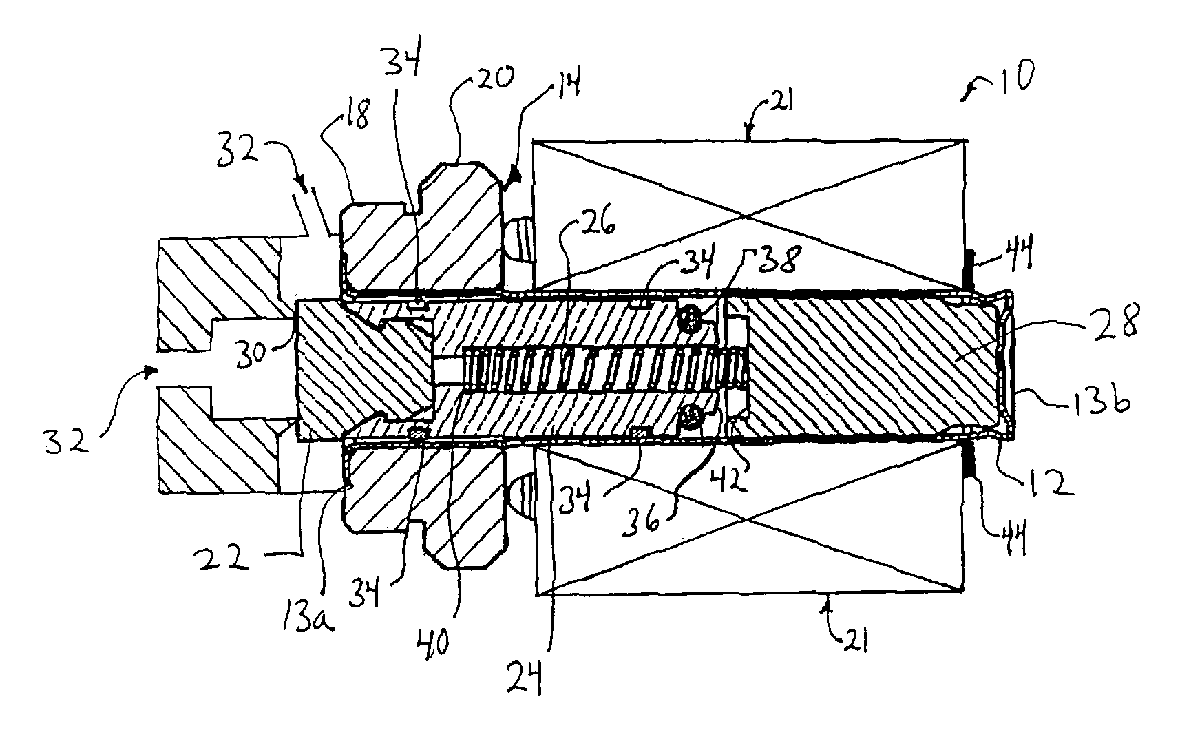
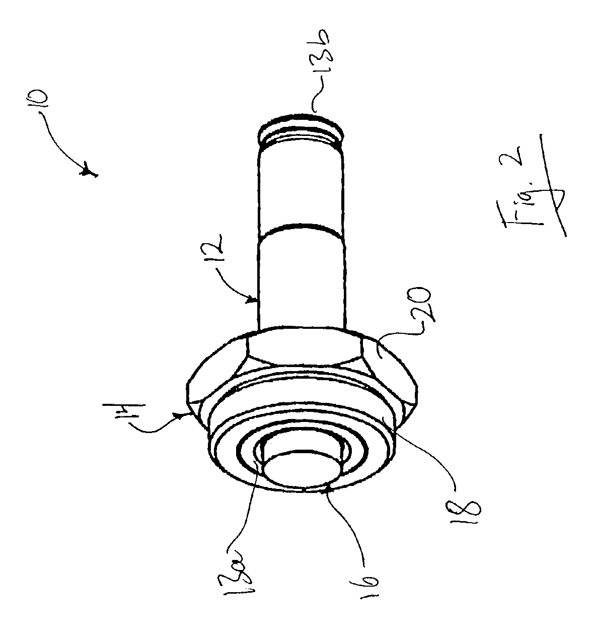
[0016]Referring to FIG. 2, there is shown the solenoid valve of the present invention. The solenoid valve 10 includes an outer casing 12, a threaded adapter 14, and an armature assembly 16.

[0017]The outer casing 12 encases the armature assembly 16 and is made of a rigid material such as brass or stainless steel. The outer casing 12 includes an open end 13a and a closed end 13b retaining plug nut member 28. The threaded adapter 14 is made of brass or plated steel. The inner surface of the threaded adapter 14 is affixed to the outer surface of the outer casing 12 at the open end 13a. The threaded adapter 14 includes a threaded outer surface 18 and a hex head 20. A solenoid coil assembly 21 (shown in FIG. 3) is mounted over the outer casing 12, between the hex head 20 and the closed end 13b.

[0018]The armature assembly, as best shown in FIG. 3, includes a BUNA-N rubber piston head 22, an armature member 24, a compression spring 26, and a plug nut 28. The piston head 22 is configured wi...


PUM


Abstract

The solenoid valve of the present invention includes an armature with a protrusion and a plug nut with a recess for receiving the protrusion. The protrusion includes a polymer o-ring. The protrusion is configured such that it slides freely within the recess. The o-ring contacts the plug nut to prevent further motion of the armature toward the plug nut after the protrusion has entered the recess.

Description

FIELD OF THE INVENTION[0001]This invention relates to solenoid valves.BACKGROUND OF THE INVENTION[0002]Conventional solenoid valves include a moveable armature and a stationary plug nut as shown in FIG. 1. A wire coil encloses the valve on the plug nut side and an external spring biases the armature against a valve seat. An electric current running through the wire coil creates a magnetic field that forces the armature against the external spring until the armature contacts the plug nut. A rubber pad is commonly glued into the recess of the plug nut to reduce wear of the armature and the plug nut. When the rubber pad must be replaced due to wear, the solenoid valve must be disassembled. Further, the heat generated by the electrical current through the coil degrades the glue used to affix the rubber pad to the plug nut. Even further, the rubber pad does not provide a proper surface for a biasing spring to abut against. Thus conventional solenoid valves require inefficient external sp...

Claims


Application Information

Patent Timeline
Patent Type & Authority Patents(United States)
IPC IPC(8): F16K31/06
CPCF16K31/0696
Inventor MCCOMBS, NORMAN R.VALVO, MICHAEL R.
Owner CAIRE
Why Eureka
Try Eureka