Sensor stripe encapsulation layer in a read/write head

a technology of read/write head and sensor stripe, which is applied in the field of read/write head, can solve the problems of mechanical damage to the exposed edge of the sensor stripe, exposed edge is also subject to oxidation and other corrosion processes, and achieves the effect of improving the stability and reliability of the read/write head

Inactive Publication Date: 2005-08-30
SEAGATE TECH LLC
View PDF15 Cites 39 Cited by
  • Summary
  • Abstract
  • Description
  • Claims
  • Application Information

AI Technical Summary

Problems solved by technology

The lapping process, however, also mechanically damages the exposed edge of the sensor stripe 162 and the exposed edge is also subject to oxidation and other corrosion processes as a result of the lapping step.

Method used


Image

  • Sensor stripe encapsulation layer in a read/write head
  • Sensor stripe encapsulation layer in a read/write head
  • Sensor stripe encapsulation layer in a read/write head

Examples


Embodiment Construction

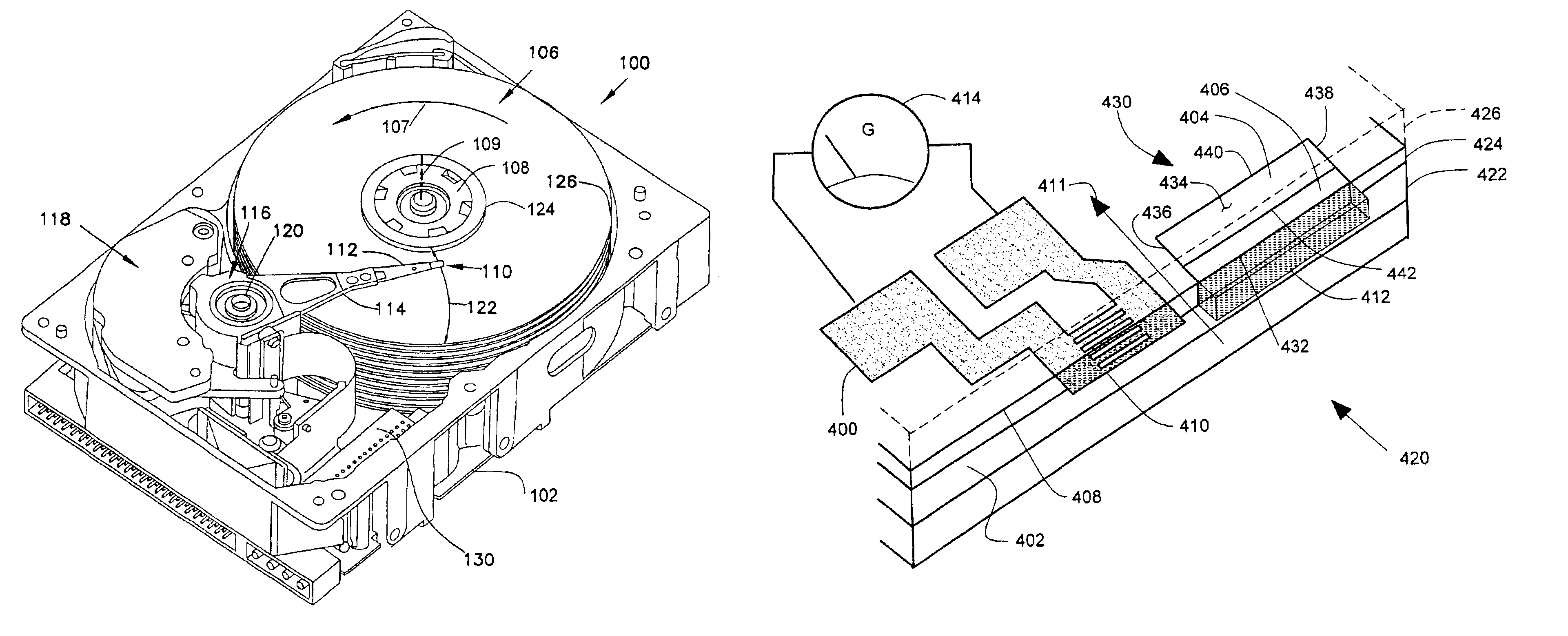
[0021]In present day read / write head processing, it is quite common to require a specified stripe height in the range of 50 nm to 100 nm. Present lapping techniques permit lapping the stripe to the specified target with a standard deviation of less than 2 nm, when stripe dimension is inferred from the electrical resistance of the sensor. Subsequent changes in sensor electrical resistance indicate the presence of oxidation to a depth of approximately 10 nm from the lapped air bearing surface, resulting in a loss of sensor performance. This exposed, potentially damaged edge of the sensor that is closest to the disc is expected, by design, to produce the largest portion of the magnetoresistive signal. Thus oxidation, corrosion, or mechanical damage of this edge has a disproportionately adverse effect on the sensor performance.

[0022]In the embodiments described below, one or both edges of the magnetoresistive sensor are finished to comply with the precise final stripe height dimension d...


PUM

PropertyMeasurementUnit
heightaaaaaaaaaa
thicknessaaaaaaaaaa
electrical conductanceaaaaaaaaaa

Abstract

A magnetoresistive read head has read head layers that are shaped to form an air bearing surface and a sensor stripe cavity with an open side at the air bearing surface. A sensor stripe is deposited in the sensor stripe cavity. The sensor stripe has a front surface that is set back from the air bearing surface to define an encapsulation cavity extending from the front surface to the air bearing surface. An encapsulation layer is deposited in the encapsulation cavity. The encapsulation layer encapsulates the front surface.

Description

FIELD OF THE INVENTION[0001]The present invention relates generally to read / write heads, and more particularly but not by limitation to a sensor stripe in a read / write head.BACKGROUND OF THE INVENTION[0002]In a common method for manufacturing magnetic recording heads for use in disk drives, each magnetoresistive sensor, or reader, and its associated magnetic writer is fabricated on a surface of a wafer as one head in an array of heads arranged in rows and columns. After completion of the wafer fabrication process, the wafers are sawed into bars, with each bar containing one row of heads. Each bar is then lapped very precisely to machine a critical “stripe height” reader dimension by mechanically removing one edge of a relatively high “stripe” feature defined lithographically in the wafer process.[0003]One problem with this mechanical lapping process is that the magnetoresistive sensor stripe typically consist of several thin layers of magnetic material that readily oxidize when expo...

Claims


Application Information

Patent Timeline
Patent Type & Authority Patents(United States)
IPC IPC(8): G11B5/39
CPCG11B5/3906Y10S451/908Y10T29/49037Y10T29/49036Y10T29/49052
Inventor BURBANK, DANIEL PAULHEIM, KEVIN RICHARD
Owner SEAGATE TECH LLC
Why Eureka
Try Eureka