Matching layer having gradient in impedance for ultrasound transducers
a technology of impedance gradient and matching layer, which is applied in the field of matching layer for ultrasound transducers, can solve the problems of increasing the attenuation of ultrasound intensity, reducing the performance of attendants, and a challenge in the manufacture of matching layer
- Summary
- Abstract
- Description
- Claims
- Application Information
AI Technical Summary
Benefits of technology
Problems solved by technology
Method used
Image
Examples
first embodiment
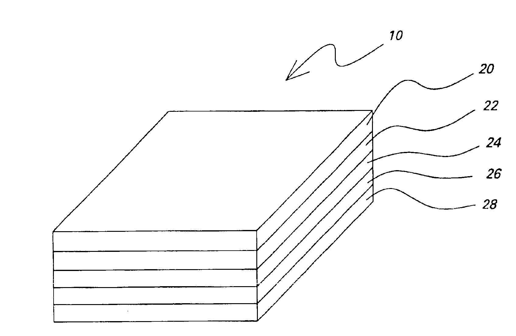
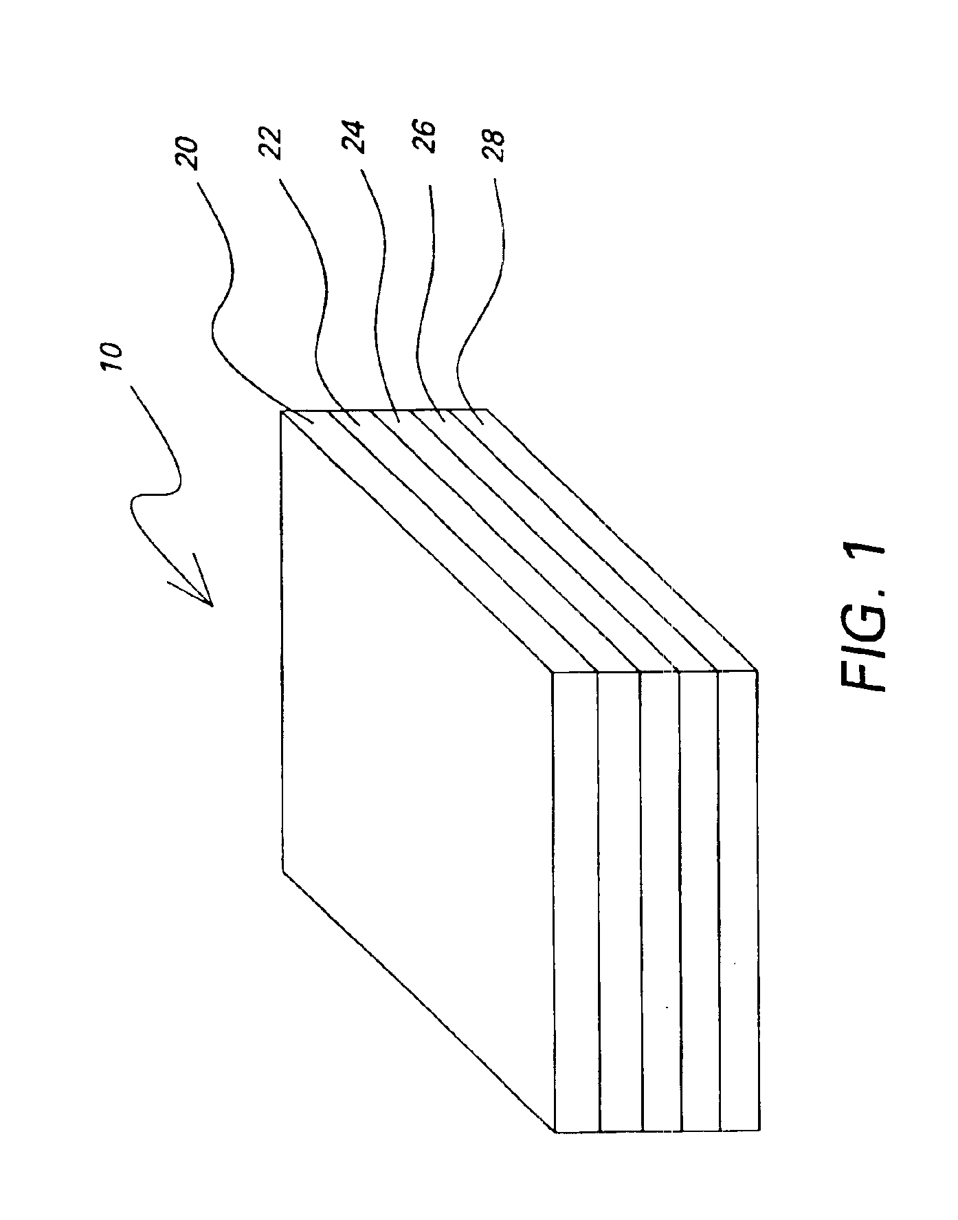
[0011]FIG. 1 shows the matching layer of the present invention. Matching layer 10 comprises a plurality of sublayers, such as shown by numerals 20-28. For example, matching layer 10 is shown to consists of five sublayers, but any number of sublayers may be used. The number of sublayers will be determined for the desired application so to balance between the increase in transmission at the target surface and the attenuation of the sound within the matching layer. Typically, this number is about 21 or fewer. The sublayers may have the same thickness or different thicknesses. The matching layer preferably has a thickness of one-quarter wavelength or an odd multiple of one-quarter wavelength of the operating frequency of the piezoelectric element when it is energized. The sublayers may be made of materials having decreasing impedance values from that of the piezoelectric element to that of the body tissue. In one embodiment of the present invention, a film of metal serving as the first ...
second embodiment
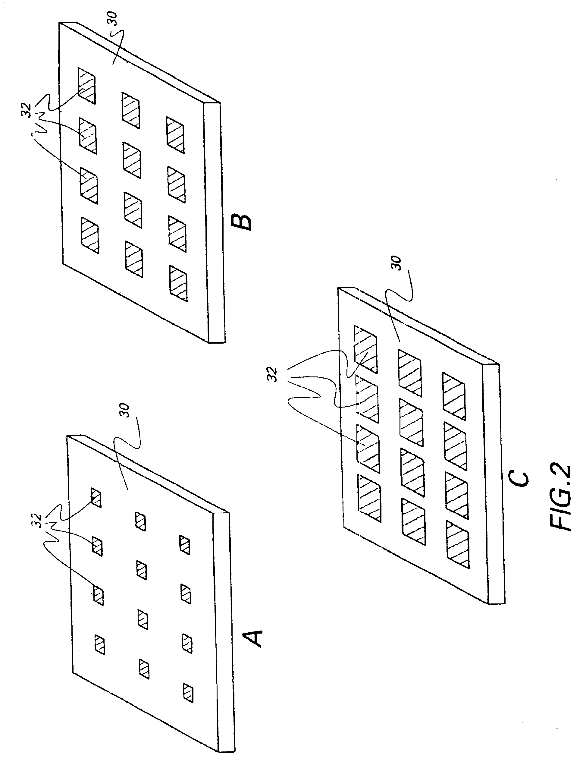
[0012]In a second embodiment, each sublayer may be formed in a pattern of different materials. For example, FIG. 2 shows a pattern of a sublayer. A first material, such as a metal, occupies the continuous area, and the second material, such as a polymer, occupies the discontinuous area, or vice versa. In addition, the total area occupied by each material may vary from one surface of the matching layer to the other surface so that the impedance values of the sublayers vary in the range from that of the transducer element material to that of the target. For example, in FIG. 2A, a material having an impedance close to that of the transducer element material occupies area 30, and a second material having an impedance close to that of the target occupies areas 32. This sublayer is positioned immediately adjacent to the transducer elements. The size of the areas 32 increases in the subsequent sublayers in the direction from the transducer elements to the target, as shown in FIGS. 2B and 2...
PUM
| Property | Measurement | Unit |
|---|---|---|
| thickness | aaaaa | aaaaa |
| thickness | aaaaa | aaaaa |
| thickness | aaaaa | aaaaa |
Abstract
Description
Claims
Application Information
 - R&D
- Intellectual Property
- Life Sciences
- Materials
- Tech Scout
- Unparalleled Data Quality
- Higher Quality Content
- 60% Fewer Hallucinations
Browse by: Latest US Patents, China's latest patents, Technical Efficacy Thesaurus, Application Domain, Technology Topic, Popular Technical Reports.
© 2025 PatSnap. All rights reserved.Legal|Privacy policy|Modern Slavery Act Transparency Statement|Sitemap|About US| Contact US: help@patsnap.com


