Performance apparatus
a technology of performance apparatus and a cylinder head, applied in the direction of automatic musical instruments, instruments, etc., can solve the problems of many mechanical noises, mechanical noises generated, and mechanical noises not negligible, and achieve the effect of reducing mechanical noise and simple construction
- Summary
- Abstract
- Description
- Claims
- Application Information
AI Technical Summary
Benefits of technology
Problems solved by technology
Method used
Image

Examples
first embodiment
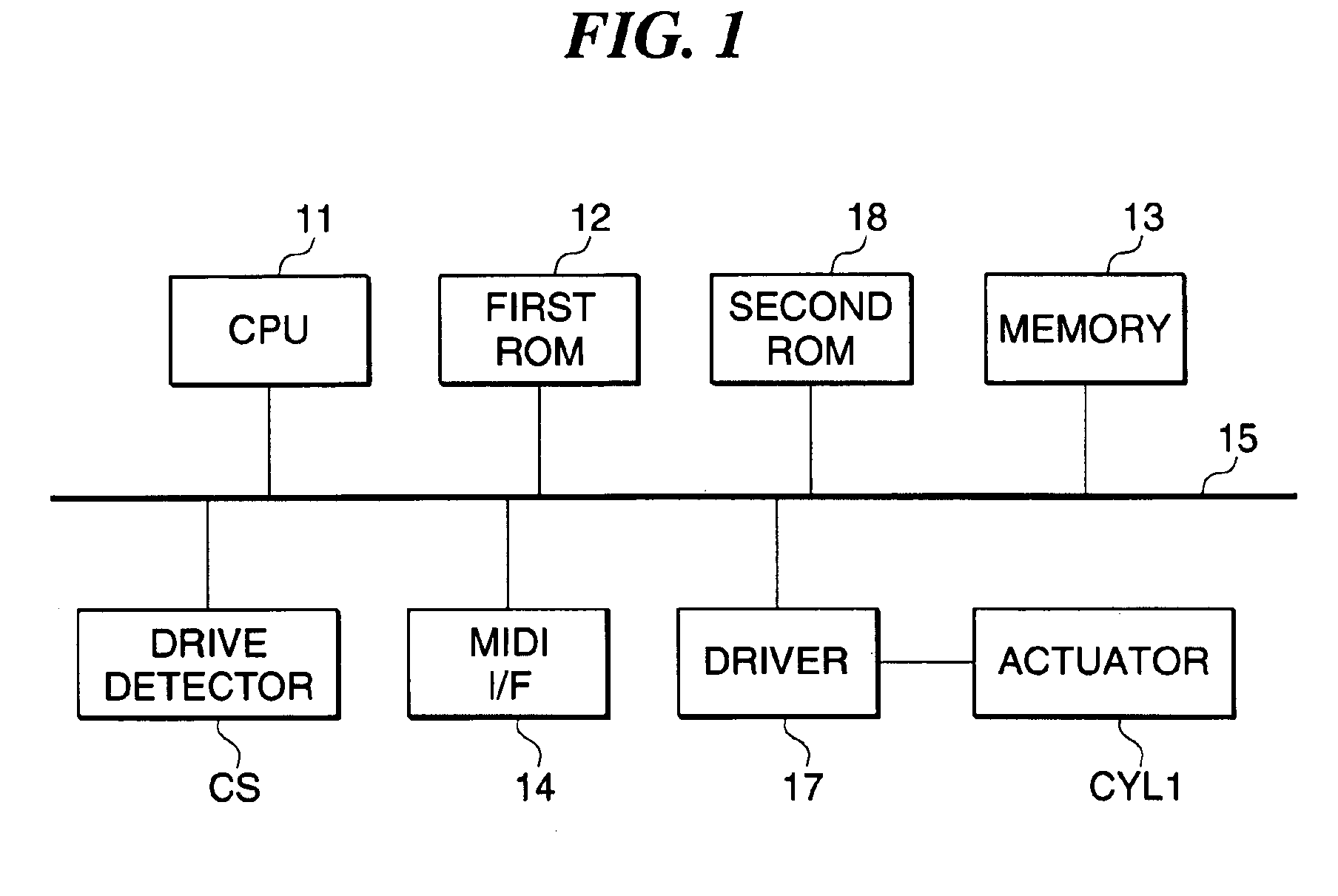
[0041]FIG. 1 is a block diagram showing the construction of a control section of a performance apparatus according to the present invention.
[0042]The performance apparatus according to the present embodiment is comprised of a first ROM 12, a memory 13, a MIDI interface (MIDI I / F) 14, a second ROM 18, drive detectors CS, and a driver 17, and a CPU 11 to which the above-mentioned component parts are connected via a bus 15. The CPU 11 controls overall operations of the performance apparatus. The first ROM 12 is comprised of a program ROM, a data ROM, and a working ROM, none of which are shown, and stores control programs to be executed by the CPU 11, various data, and so forth. The MIDI I / F 14 receives performance data inputted from MIDI equipment, not shown, or the like as MIDI (Musical Instrument Digital Interface) signals. The memory 13 is comprised of a RAM or the like, and stores various data such as performance data and can store performance data inputted from the MIDI I / F 14. Th...
second embodiment
[0079]A description will now be given of the present invention.
[0080]The present embodiment is identical with the above described first embodiment except that the rotary pick 66 is provided with reed dampers.
[0081]FIG. 7A is a side view showing the construction of the rotary pick 66 in a performance apparatus according to the second embodiment, and FIG. 7B is a fragmentary perspective view showing the appearance of the rotary pick 66.
[0082]Reed dampers 98 are attached to the rotary pick 66 in association with the four driving nails 66a, respectively, and fixed to the rotary pick 6 by an adhesive or the like. The reed dampers 98 are each formed of an elastic material such as rubber, and are disposed in front of the respective driving nails 66a in the rotational direction of the rotary pick 66 and at a location where it comes into contact with the reed 61 immediately before the driving nail 66a plucks the reed 61. Each reed damper 98 is formed to be slightly shorter than the driving n...
third embodiment
[0087]A description will now be given of the present invention with reference to FIGS. 1, 6, 8, and 9A to 9C.
[0088]FIG. 8 is a top plan view of a performance apparatus according to the third embodiment of the present invention.
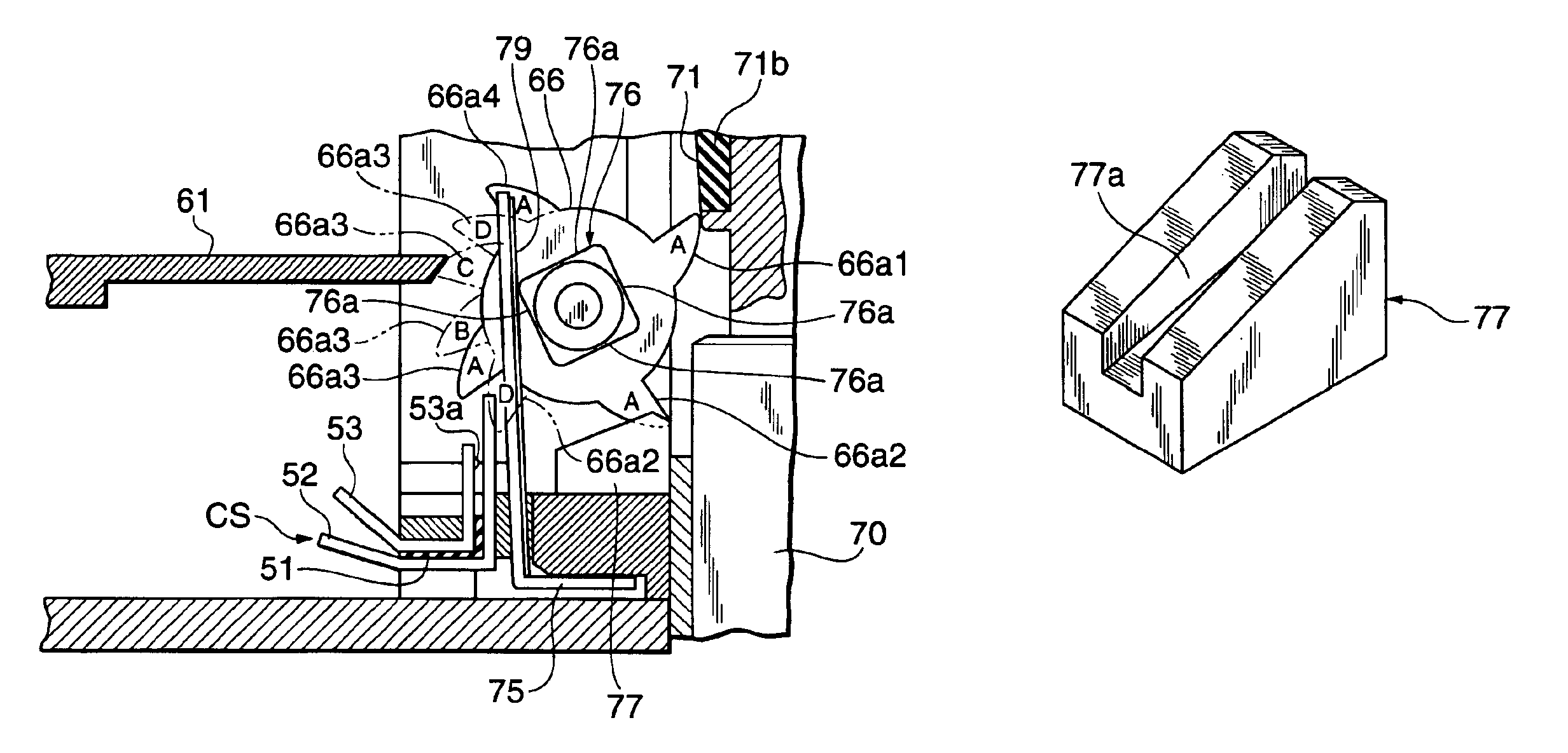
[0089]FIG. 9A is a sectional view of this apparatus. FIG. 9B is a front view showing essential parts of the apparatus as viewed from the left side in FIG. 9A. FIG. 9C is an enlarged fragmentary view of a channel-shaped stepped space and a driving nail of a rotary pick.
[0090]In the present embodiment, the construction of the control section is basically the same as in the first embodiment shown in FIG. 1. However, an actuator FLAT2, which is implemented by a flat coil type, is employed in place of the actuator CYL1. Further, a drive detector CS2 is employed in place of the drive detector CS. The actuator FLAT2 is drivingly controlled by pulse width modulation (PWM) as is the case with the first embodiment.
[0091]As shown in FIG. 8, a plurality of reeds 83, which...
PUM
 Abstract
Description
Claims
Application Information
 - R&D
- Intellectual Property
- Life Sciences
- Materials
- Tech Scout
- Unparalleled Data Quality
- Higher Quality Content
- 60% Fewer Hallucinations
Browse by: Latest US Patents, China's latest patents, Technical Efficacy Thesaurus, Application Domain, Technology Topic, Popular Technical Reports.
© 2025 PatSnap. All rights reserved.Legal|Privacy policy|Modern Slavery Act Transparency Statement|Sitemap|About US| Contact US: help@patsnap.com