
Single-transistor-clocked flip-flop

a single-transistor, flip-flop technology, applied in logic circuits, pulse generators, pulse techniques, etc., can solve the problems of large power consumption of modern processors, constant power consumption of processor clock systems, flip-flops and latches, etc., and achieve the effect of fewer transistors and easy construction

Inactive Publication Date: 2005-08-30
UNIV OF LAUSIANA AT LAFAYETTE
View PDF21 Cites 30 Cited by
  • Summary
  • Abstract
  • Description
  • Claims
  • Application Information

AI Technical Summary

Benefits of technology

[0026]Advantage of the invention is that it uses fewer transistors.

Problems solved by technology

Power consumption is a constant concern in modern processors.
Processor clock systems, consisting of flip-flops and latches, consume a large amount of power in modern processors.
The clocked transistors within a flip-flop have 100% switch activity and present a huge load on the clock distribution network.
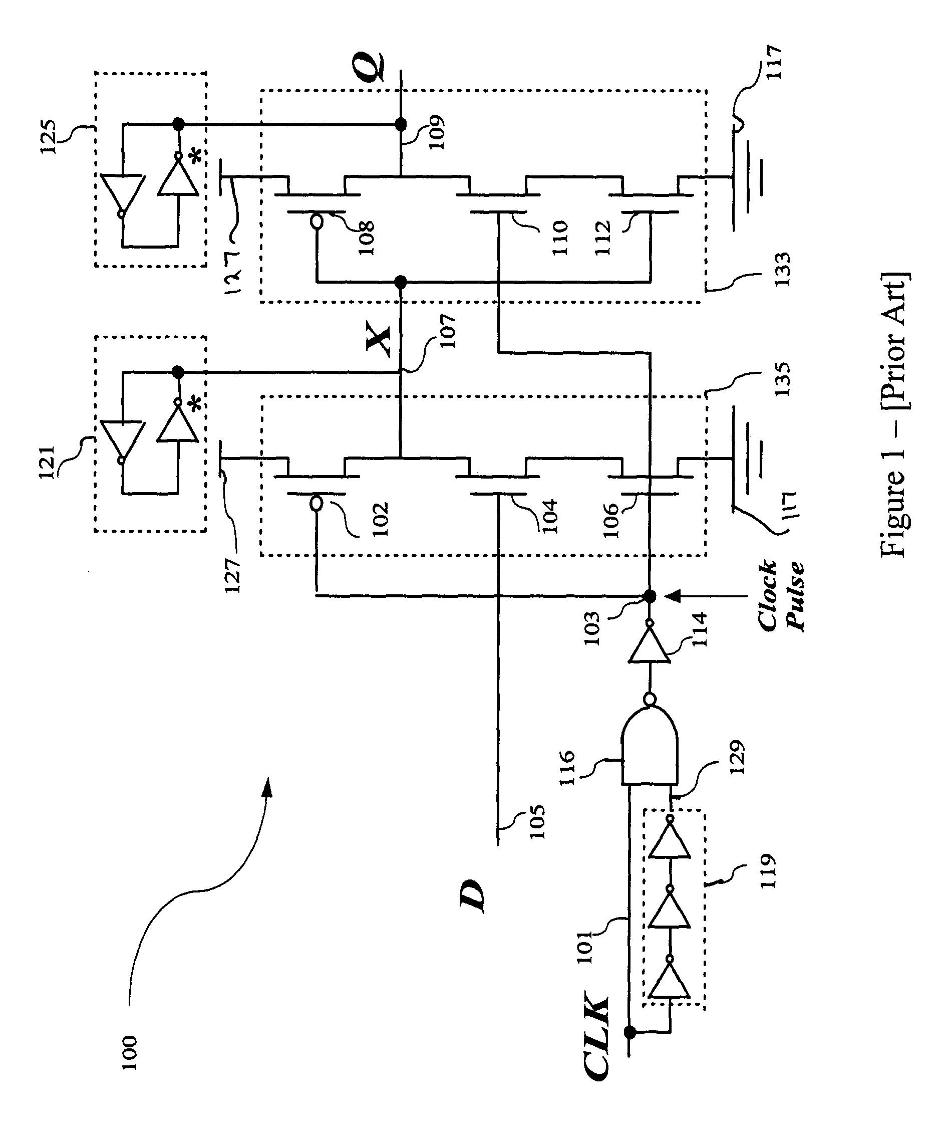
While flip-flop 100 is adequate for performing the clock function in a processor, it has limitations.
This undesirable switching activity occurs because node 107 is pre-charging and discharging even when D is kept high.
Additionally, glitches appear at the output node that could cause noise problems in the subsequent circuits.
Additionally, ep-DCO 100 consumes relatively large amounts of power because of the three clocked transistors that are used.

Method used


Image

  • Single-transistor-clocked flip-flop
  • Single-transistor-clocked flip-flop
  • Single-transistor-clocked flip-flop

Examples


Embodiment Construction

[0033]In the following detailed description of the embodiments reference is made to the accompanying drawings. The drawings are intended to show, by way of illustration, specific embodiments in which the invention may be practiced. It is to be understood that other embodiments of the invention may be utilized and structural changes may be made without departing from the scope of the present invention.

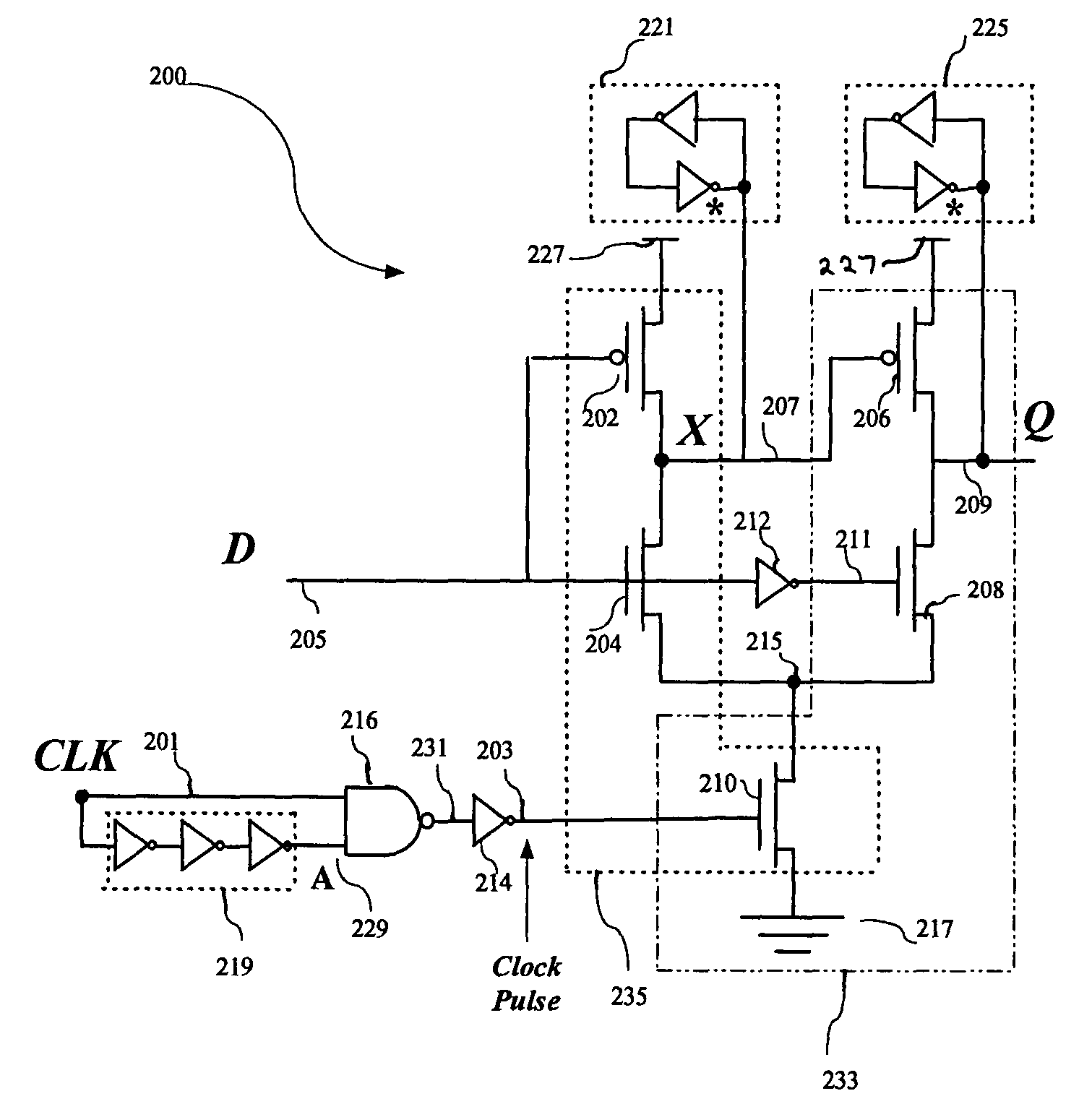
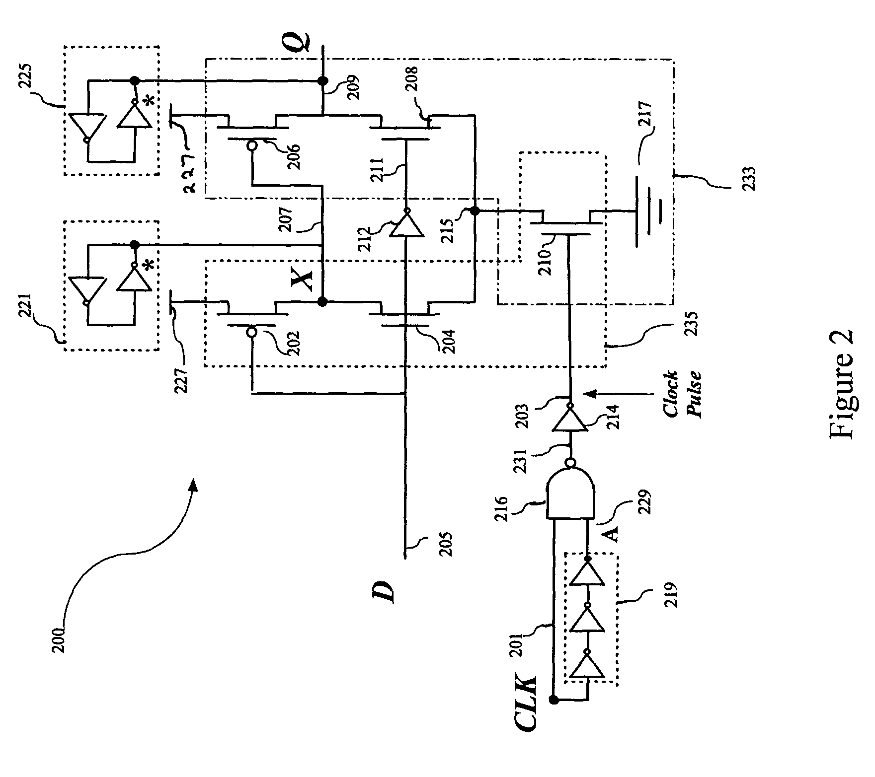
[0034]Referring to FIG. 2, a flip-flop is shown that is an embodiment of the present invention. Flip-flop 200 comprises first branch 235, second branch 233, and pulse generator 240 (includes components 214, 216, 219). First branch 235 includes first branch transistors 202, 204 and shared transistor 210 connecting in series between first node 227, which is coupled to a high or logic one potential, and a second node 217 which is coupled to a low, or logic zero potential. Second branch 233 is provided and shares shared transistor 210 with first branch 235. In addition to shared transistor ...


PUM


Abstract

The invention provides a low power, high performance flip-flop. The flip-flop uses only one clocked transistor. The single clocked transistor is shared by the first and second branches of the device. A pulse generator produces a clock pulse to trigger the flip-flop. In one preferred embodiment the device can be made as a static explicit pulsed flip-flop which employs only two clocked transistors.

Description

STATEMENT REGARDING FEDERALLY SPONSORED RESEARCH OR DEVELOPMENT[0001]This invention was funded in part by the Department of Energy under the EETAPP program, DE97ER12220.CROSS REFERENCE TO RELATED APPLICATIONS[0002]Not Applicable.REFERENCE TO A “SEQUENCE LISTING,” A TABLE, OR A COMPUTER PROGRAM[0003]Not Applicable.BACKGROUND OF THE INVENTION[0004]1. Field of the Invention[0005]The present invention relates to clocked circuits for processors. More particularly, the invention relates to a single-transistor-clocked circuit, more especially to a single-transistor-clocked flip-flop.[0006]2. Description of Related Art[0007]Power consumption is a constant concern in modern processors. Processor clock systems, consisting of flip-flops and latches, consume a large amount of power in modern processors. The clocked transistors within a flip-flop have 100% switch activity and present a huge load on the clock distribution network. If one can reduce the number of clocked transistors in a flip-flop...

Claims


Application Information

Patent Timeline
Patent Type & Authority Patents(United States)
IPC IPC(8): H03K3/356H03K3/00
CPCH03K3/356156
Inventor ZHAO, PEIYIDARWISH, TAREKBAYOUMI, MAGDY
Owner UNIV OF LAUSIANA AT LAFAYETTE
Learn More