Scanned beam display

a beam display and scanning beam technology, applied in the field of low light viewing systems, can solve the problems of mass inducing forces on users, screen b>42/b> typically outputs monochrome light with limited resolution and limited contrast, and users often take time to acclima

Inactive Publication Date: 2005-08-30
MICROVISION
View PDF29 Cites 96 Cited by
  • Summary
  • Abstract
  • Description
  • Claims
  • Application Information

AI Technical Summary

Benefits of technology

[0014]In response to the incident infrared light, the IIT outputs visible light for viewing by a user. To prevent environmental light from affecting the IIT, the input to the IIT is occluded, in one embodiment.

Problems solved by technology

Additionally, the screen 42 typically outputs monochrome light with limited resolution and limited contrast.
Moreover, NVGs often have a limited depth of field and a narrow field of view, giving the user a perception of “tunnel vision.” The overall optical effects of distortion, monochromaticity, limited contrast, limited depth of field and limited field of view often require users to practice operating with NVGs before attempting critical activities.
In addition to optical effects, users often take time to acclimate to the physical presence of NVGs.
The added mass induces forces on the user that may affect the user's physical movements and balance.
Because the combined optical and physical effects can degrade a user's performance significantly, some form of NVG training is often required before the user engages in difficult or dangerous activities.
The fiber rod system requires the IIT to be removed and does not provide light at the output wavelength of the cathodoluminescent layer.
Additionally, the fiber rod system does not appear to provide a way to provide electronically generated images.
This system has several drawbacks, including limiting the user's movement and orientation to locations where the screen is visible through the NVG.
Unfortunately, for such location, the user may interrupt the projected light as the user moves about the artificial environment.

Method used


Image

  • Scanned beam display
  • Scanned beam display
  • Scanned beam display

Examples


Embodiment Construction

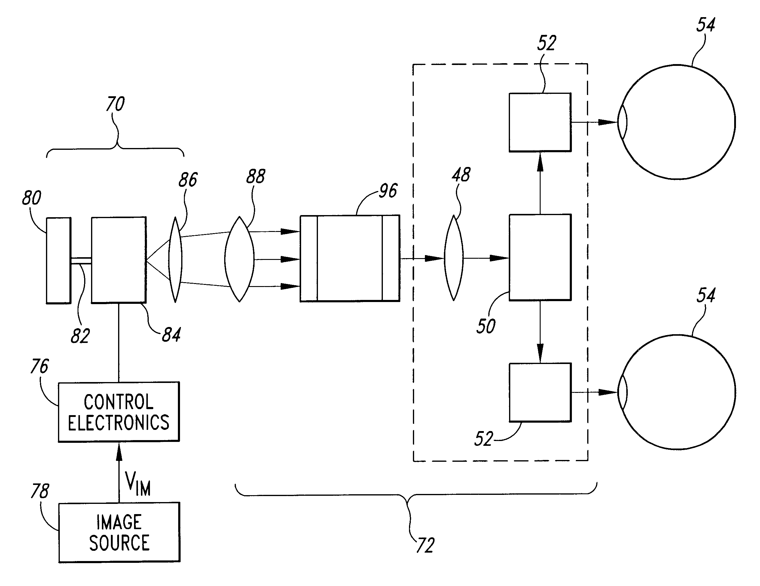
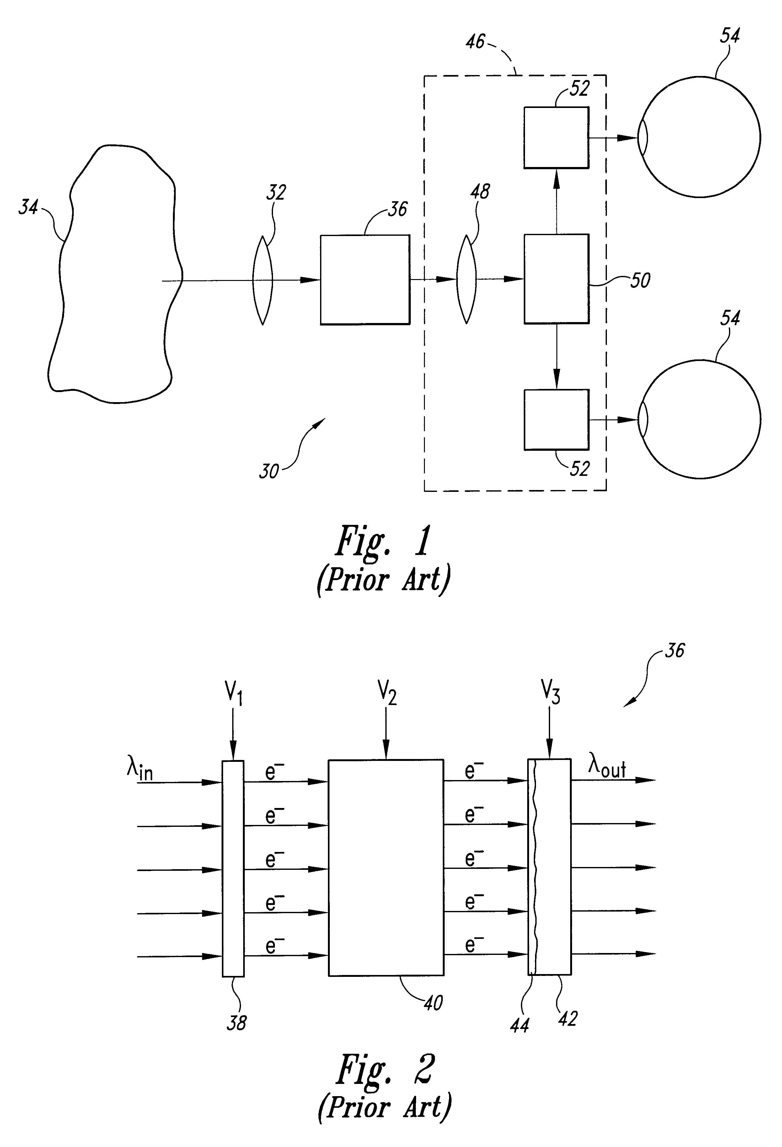
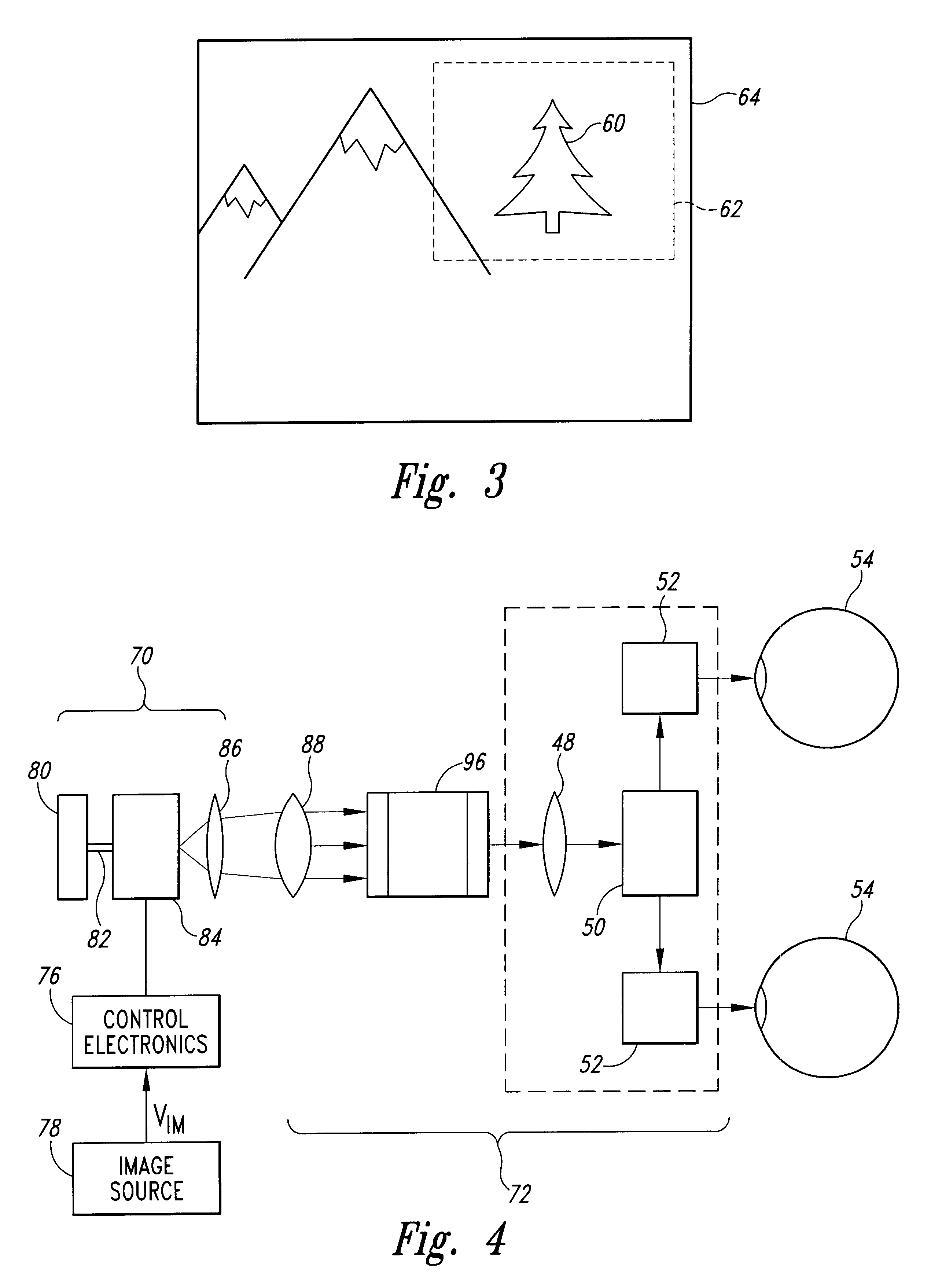
[0033]A variety of techniques are available for providing visual displays of graphical or video images to a user. Recently, very small displays have been developed for partial or augmented view applications. In such applications, the display is positioned to produce an image 60 in a region 62 of a user's field of view 64, as shown in FIG. 3. The user can thus see both a displayed image 66 and background information 68.

[0034]One example of a small display is a scanned beam display such as that described in U.S. Pat. No. 5,467,104 of Furness et al., entitled VIRTUAL RETINAL DISPLAY, which is incorporated herein by reference. In scanned displays, a scanner, such as a scanning mirror or acousto-optic scanner, scans a modulated light beam onto a viewer's retina. The scanned light enters the eye through the viewer's pupil and is imaged onto the retina by the cornea. The user perceives an image corresponding to the modulated light image onto the retina. Other examples of small displays inc...


PUM


Abstract

A display apparatus includes first and second IR or other light sources that produce light at respective first and second non-visible wavelengths. The light is modulated according to a desired image. The modulated light is then applied to a wavelength selective phosphor that converts each component of the light to a respective visible wavelength. In one embodiment, the image source is a scanned light beam display that scans an IR light beam onto a screen that carries the phosphor.

Description

RELATED APPLICATIONS[0001]This application is a continuation of application Ser. No. 09 / 144,400, filed Aug. 31, 1998 now abandoned. It is also a continuation-in-part of U.S. patent application Ser. No. 09 / 129,619, filed Aug. 5, 1998 now abandoned.TECHNICAL FIELD[0002]The present invention relates to low light viewing systems and, more particularly, to low light viewing systems that produce simulated images for a user.BACKGROUND OF THE INVENTION[0003]Low light vision devices are widely used in a variety of applications, such as night vision goggles (“NVGs”). NVGs allow military, police, or other persons to view objects in nighttime or low light environments.[0004]A typical night vision goggle employs an image intensifier tube (IIT) that produces a visible image in response to light from the environment. To produce the visible image, the image intensifier tube converts visible or non-visible radiation from the environment to visible light at a wavelength readily perceivable by a user....

Claims


Application Information

Patent Timeline
Patent Type & Authority Patents(United States)
IPC IPC(8): G02B23/00G02B23/12
CPCG02B23/12
Inventor LIPPERT, THOMAS M.TEGREENE, CLARENCE T.
Owner MICROVISION
Why Eureka
Try Eureka