Communication device and communication control method using lower layer data transmission order control at upper layer

a communication control and communication control technology, applied in data switching networks, instruments, frequency-division multiplexes, etc., can solve the problems of data transmission delay, data transmission delay, data loss compensation function wasteful execution, etc., to achieve the effect of suppressing the execution of data loss compensation function

Inactive Publication Date: 2005-08-30
KK TOSHIBA
View PDF7 Cites 27 Cited by
  • Summary
  • Abstract
  • Description
  • Claims
  • Application Information

AI Technical Summary

Benefits of technology

[0012]It is therefore an object of the present invention to provide a communication device and a communication control method for the case of carrying out communications using a communication protocol with data loss compensation functions provided at both upper and lower layers, which are capable of suppressing the wasteful execution of the data loss compensation function at the upper layer even when the transmission delay is increased by the data loss compensation function at the lower layer.

Problems solved by technology

At the link layer adopting the data loss compensation function, when data are re-transmitted for the purpose of compensating the data loss, the data transmission delay will be increased considerably during that time.
The data transmission delay is also affected by the change of the redundancy for the purpose of the error correction used at the link layer.
For these reasons, when the TCP / IP (Transmission Control Protocol / Internet Protocol) with the data loss compensation function is used as an upper layer protocol, for example, it is known that there is a possibility for a time-out re-transmission of the TCP to occur due to a variation of the transmission delay caused at the link layer.
On the other hand, most of the data loss can be compensated at the link layer so that the re-transmission by the TCP is actually unnecessary in many cases, and the re-transmission may cause wasteful consumption of the channel capacity.
As a result, there is little possibility for a transmission of other packets to interrupt the continuous transmission of packets of a specific TCP connection.
Consequently, there is a tendency for packets of the same TCP connection to be transmitted in lumps.
For this reason, the transmission delay is increased considerably during that time.
However, as the channel is occupied for a relatively long period of time by the TCP connection A, the TCP transmission terminal cannot receive ACK from any TCP connections other than the TCP connection A during this period of time.
Then, when the bursty errors occur, the transmission delay becomes large abruptly so that the adaptive control of the time-out value of the TCP cannot keep up with the change and the possibility for the time-out re-transmission to occur becomes high.

Method used


Image

  • Communication device and communication control method using lower layer data transmission order control at upper layer
  • Communication device and communication control method using lower layer data transmission order control at upper layer
  • Communication device and communication control method using lower layer data transmission order control at upper layer

Examples


first embodiment

[0034]Referring now to FIG. 1 to FIG. 16, a communication device and a communication control method according to the present invention will be described in detail. In the following description, the same or similar parts will be given the same or similar reference numerals in the drawings.

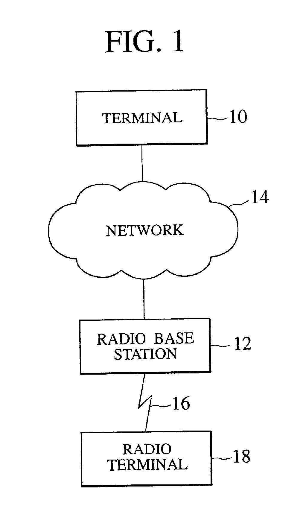
[0035]FIG. 1 shows an exemplary configuration of a network system according to the first embodiment of the present invention.

[0036]In the network system of FIG. 1, a terminal 10 and a radio base station 12 are connected through a network 14 having an IP packet delivery function. The radio base station 12 accommodates a radio terminal 18 using a radio channel 16. The terminal 10 and the radio terminal 18 can exchange IP packets through the network 14, the radio base station 12 and the radio channel 16. In the following, the exemplary case of the data transmission by the TCP from the terminal 10 to the radio terminal 18 will be described.

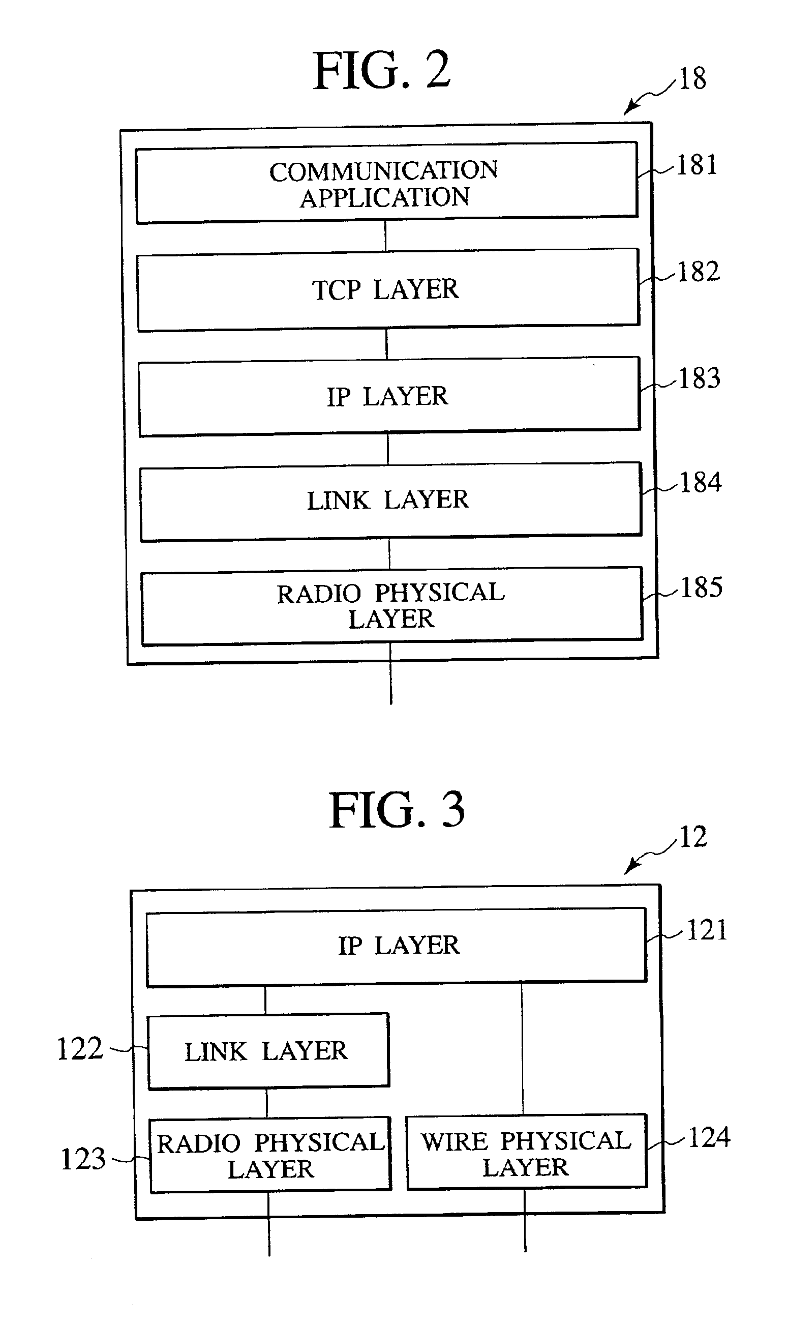
[0037]FIG. 2 shows a protocol configuration of the radio termina...

second embodiment

[0041]FIG. 4 shows a functional configuration suitable for both the link layer 184 of FIG. 2 and the link layer 122 of FIG. 3. The functional configuration of FIG. 4 comprises an upper layer 20, a transmission packet storage function 22, an identification function 24, a packet assembling function 26, a mode determination function 28, a frame formation function 30, a transmission packet selection function 32, a received frame storage function 34, an acknowledgement reception function 36, a frame transmission function 38, an acknowledgement transmission function 40, a frame reception function 42, a radio channel interface 44, and an upper layer congestion control function 46. The upper layer congestion control function 46 will be described in the second embodiment to be described below.

[0042]In FIG. 4, the upper layer 20 corresponds to the IP layer 183 of FIG. 2 and the IP layer 121 of FIG. 3, and the radio channel interface 44 corresponds to the radio physical layer 185 of FIG. 2 and...


PUM


Abstract

In a communication device using a communication protocol with data loss compensation functions provided at both an upper layer and a lower layer, a transmission order among packets to be transmitted is controlled at the lower layer, according to the transmission states of upper layer connections to which the packets belong, such that when there is at least one non-transmitted packet for each one of at least two different upper layer connections, at least two packets to be transmitted consecutively are belonging to different upper layer connections.

Description

BACKGROUND OF THE INVENTION[0001]1. Field of the Invention[0002]The present invention relates to a communication device and a communication control method using a communication protocol with data loss compensation functions provided at both upper and lower layers.[0003]2. Description of the Related Art[0004]In the case of transmitting data through unstable channels such as radio transmission paths in which errors can occur at a high probability, it is customary to provide functions for data re-transmission, error correction, etc., on a link layer protocol for the purpose of compensating the data loss due to channel errors.[0005]At the link layer adopting the data loss compensation function, when data are re-transmitted for the purpose of compensating the data loss, the data transmission delay will be increased considerably during that time. The data transmission delay is also affected by the change of the redundancy for the purpose of the error correction used at the link layer. For...

Claims


Application Information

Patent Timeline
Patent Type & Authority Patents(United States)
IPC IPC(8): H04L1/16H04L1/18H04L29/06H04L1/00H04L29/02
CPCH04L1/1664H04L1/1874H04L1/1887H04L69/16H04L69/161H04L69/163H04L1/004H04L1/1803H04L1/1806H04L1/1809
Inventor TAKAGI, MASAHIRO
Owner KK TOSHIBA
Why Eureka
Try Eureka