
Adjustable probe

Inactive Publication Date: 2005-09-06
TESA SE
View PDF16 Cites 16 Cited by
  • Summary
  • Abstract
  • Description
  • Claims
  • Application Information

AI Technical Summary

Benefits of technology

[0014]a mobile element capable of turning around an axis; a resilient device for holding said mobile element in a locked position, preventing said mobile element from moving; an actuator, opposed to said resilient device, for disengaging said mobile element by displacement in the direction of said axis, allowing said first mobile element to rotate around said axis; a force transmission mechanism designed to supply an increasing demultiplication ratio for reducing the intensity of the force required for holding said mobile element in disengaged position.

Problems solved by technology

When the probe is used for measuring pieces of complex shape with hollows and protuberances, it is difficult, if not impossible, to bring the feeler into contact with the whole surface of the piece without the probe's fixed part or the feeler's rod interfering with the elements of the piece to be measured.
These operations can entail positioning errors, for example following an involuntary movement of the first axis during positioning of the second axis.
Another inconvenient of the probe described here above is that the locking and unlocking operations require an external torque to be applied onto the locking wheel, which is transmitted by the probe and its support to the mobile arm of the measuring machine.
This net torque causes mechanical efforts on the probe's support and can cause the whole probe to move.
To avoid this inconvenient, the user must hold the probe motionless when acting on the locking wheel, which makes it difficult or even impossible to perform this operation with a single hand.

Method used


Image

  • Adjustable probe
  • Adjustable probe
  • Adjustable probe

Examples


first embodiment

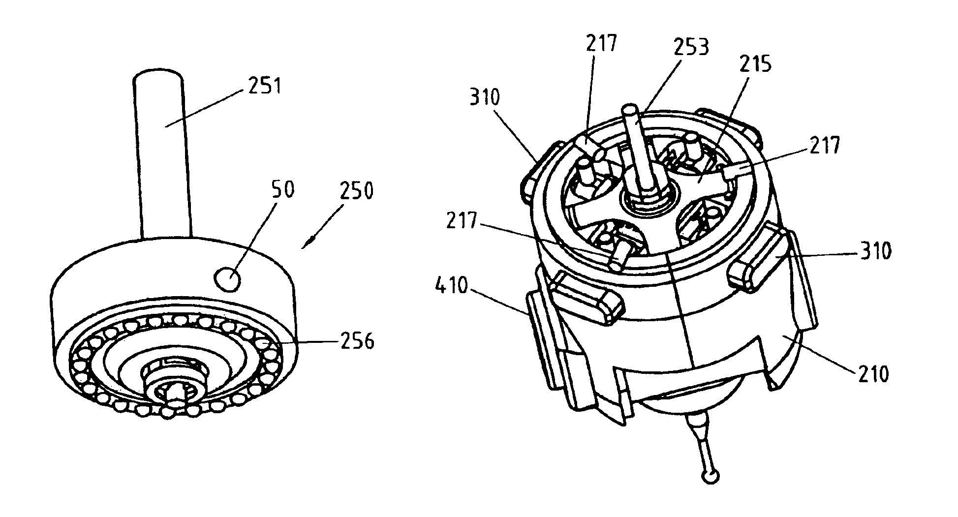
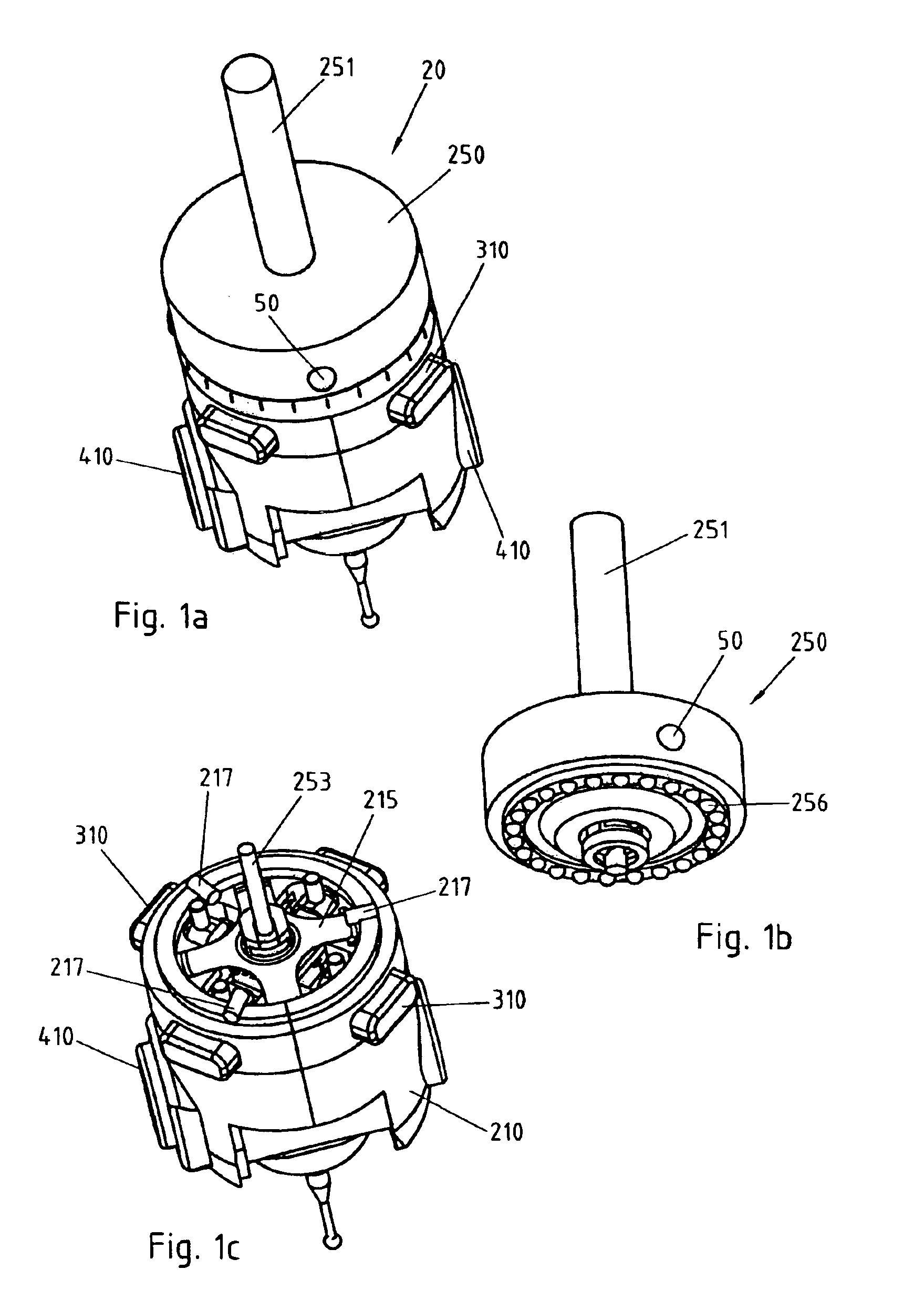
[0022]the invention represented in FIGS. 1a to 1e is a touch-triggered probe 20 comprising a fixed part 250, represented in detail in FIG. 1b, and designed to be fastened to the mobile arm of a measuring machine through the threaded rod 251 or through any other known fastening means.

[0023]The fixed part 250 carries on its lower side 24 spheres 256, regularly distributed along a circumference and partially protruding downwards. The spheres 256 define 24 indexed positions at a distance of 15 degrees for the probe's first rotation axis, as will be explained further below. It is obvious that a different number of spheres can be used according to the desired number of indexed positions.

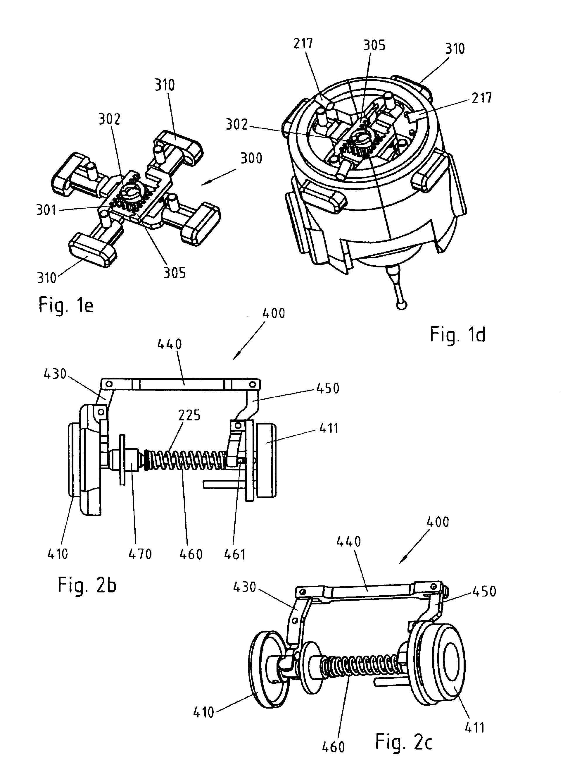
[0024]The mobile element 210, represented in FIGS. 1c and 1d, carries on its upper side three cylindrical pins 217. The flat spring 215 presses the mobile element 210 against the fixed element 250. In this situation, each of the pins 217 rests on two of the spheres 256, the six resulting contact points det...

second embodiment

[0046]FIGS. 4, 5a and 5b show the invention, in which the disengaging mechanism 300 of the first axis 211 is achieved with four pairs of identical and symmetrical connecting rods 320.

[0047]In this embodiment, each pair of connecting rods 320 is articulated relative to a central point 323 and the external forces applied to the buttons 310 are transmitted to said central points 323 when the two ends of the two connecting rods of a pair rest one on the fixed element 250 and the other on the first mobile element 210.

[0048]In this disposition, the reduction ratio between the axial force exerted on the mobile element 210 and the radial operation force applied to the buttons 310 is proportional to the tangent of the half aperture angle between the connecting rods 320. There results a reduction ratio that increases with the distance between the elements 250 and 210 and the angle between the connecting rods 320. This variability of the reduction ratio is advantageous since the force required...


PUM


Abstract

Touch-triggered probe comprising a fixed part, designed to be fastened onto a measuring machine or a machine tool, and a mobile contact feeler that can be oriented on two independent axes along a multiplicity of spatial directions. The two axes of the probe comprise each an actuator for unlocking and adjusting the axes. The operation force is reduced as compared with the high effective indexing force by a demultiplying mechanism having an increasing transmission ratio, for making easier the operation in unlocked position. The indication elements can easily be read whatever the feeler's orientation.

Description

REFERENCE DATA[0001]This application claims priority from European patent applications No. EP03001836.0 filed on Jan. 29, 2003 and No. EP03100525.9 filed on Mar. 3, 2003.FIELD OF THE INVENTION[0002]The present invention concerns a touch-triggered probe that can be oriented spatially along a multiplicity of directions. This probe is designed to be used more particularly, but not exclusively, in a hand-operated or automatic measuring machine or in a machine tool such as for example a milling machine, for the three-dimensional measuring of a piece that has been or is being machined.DESCRIPTION OF RELATED ART[0003]Touch-triggered probes are measuring instruments used widely, though not exclusively, on production lines of mechanical pieces for accurately checking the dimensions or surfaces of the mechanical pieces. Touch-triggered probes are also used for three-dimensional measuring of pieces of complex shape in order to reproduce or model them.[0004]Generally, touch-triggered probes com...

Claims


Application Information

Patent Timeline
IPC IPC(8): G01B7/012G01B7/016G01B5/00G01B21/02G01B3/00G01B11/00G01B21/04G01B7/008G01B5/008G01B5/016G01B5/012
CPCG01B5/012
Inventor ROUGE, CLAUDEJORDIL, PASCALZANIER, ADRIANO
Owner TESA SE
Features
  • Generate Ideas
  • Intellectual Property
  • Life Sciences
  • Materials
  • Tech Scout
  • Unparalleled Data Quality
  • Higher Quality Content
  • 60% Fewer Hallucinations
Learn More