Gauge mounting assembly

a technology for mounting assemblies and gauges, applied in the field of apparatus, can solve the problems of not being able to achieve ergonomically correct positioning, lack of desired controls, indications, accessories, etc., and achieve the effect of convenient installation and adjustmen

Inactive Publication Date: 2005-09-06
GAUGE WORKS
View PDF32 Cites 37 Cited by
  • Summary
  • Abstract
  • Description
  • Claims
  • Application Information

AI Technical Summary

Benefits of technology

[0016]The present invention is directed to a gauge mount with increased flexibility of positioning and consistent or improved rigidity. To attain this, the present invention comprises a base member that secures to a vehicle surface and provides a spherical or ball member at a desired location, along with a ball clamp for gripping the ball member. A gauge frame member for receiving a gauge or other indicator can be attached to the ball clamp. The base member hosts the ball member in a position suited for the application; for example, spatial compatibility may dictate a central positioning of a tachometer for a motorcycle. The gauge frame member can be one of a number of designs appropriate for the gauge or accessory.
[0020]It is therefore an object of the present invention to provide a mounting assembly for gauges, controls, or other items that is adjustable and rigid.
[0022]It is yet another object of the present invention to provide a gauge mount that is easy to install and adjust.

Problems solved by technology

Some forms of personal transportation lack desired controls, indications, or accessories.
Vehicles such as bicycles or snowmobiles offer little space typically considered suitable for instrumentation.
Because of the expense of design and production, after-market manufacturers try to design products applicable to a wide variety of makes or styles of vehicles.
If a gauge mount is not adjustable, then it may not permit ergonomically correct positioning.
This approach is limited in several ways.
First, the positioning is limited to the location and availability of the mounting bolt or bolts, possibly inhibiting good spatial compatibility.
Second, the installation requires removing a bolt, possibly from the handlebar or front suspension; novice mechanics may be uncomfortable undertaking this task.
Third, it is possible that the added thickness of the bracket could impede the proper functioning of the mounting bolt if its threads are no longer able to engage.
These solutions often involve a tradeoff between spatial compatibility and vehicle applicability.
For example, a pod designed to be in the driver's view when placed on the curved dash of a subcompact car is unlikely to be suitable for the straight dash of a large sedan.
In general, however, static mounts are limited in their ability to achieve spatial compatibility for a wide variety of drivers.
The problem with this approach is gripping the tube in a rigid manner, while offering flexibility in adjustment.
Depending on the orientation and shape of the bar, for example, single split clamps can also suffer from uneven distribution of compressive forces, reducing the friction available to hold the gauge in place.
This design limits the range of positions available for the gauge.
The mounting of this gripping member offers some ability to rotate for adjustment, but the housing must retain the gripping member within its mount, which limits its rotation when it is “gripping” or holding a cylindrical object like a flashlight.
However, it would pose several problems if one tried to adapt the Maglica arrangement for use with a gauge.
For the reasons discussed above, these adaptations are likely to reduce further its functionality.
This approach shares the drawback with single fasteners described above, in that any loosening of the handlebar clamp would similarly loosen the force on the floating ball until it is ultimately released from the housing.
Likewise, loosening the housing to adjust the “gripping” member could result in a loss of grip on the handlebars.
The Iteya design, like the Maglica design, is limited in that it involves inserting an item within the spherical ring, restricting its range of motion.
Aside from the single fastener weakness described above, these designs need a compressive housing to keep the sphere steady under the torque of a gauge positioned at the end of this neck.
At the same time, this housing limits the range of motion for gauge adjustment.
None of these designs offers both rigidity and a wide range of flexibility.

Method used


Image

  • Gauge mounting assembly
  • Gauge mounting assembly
  • Gauge mounting assembly

Examples


Embodiment Construction

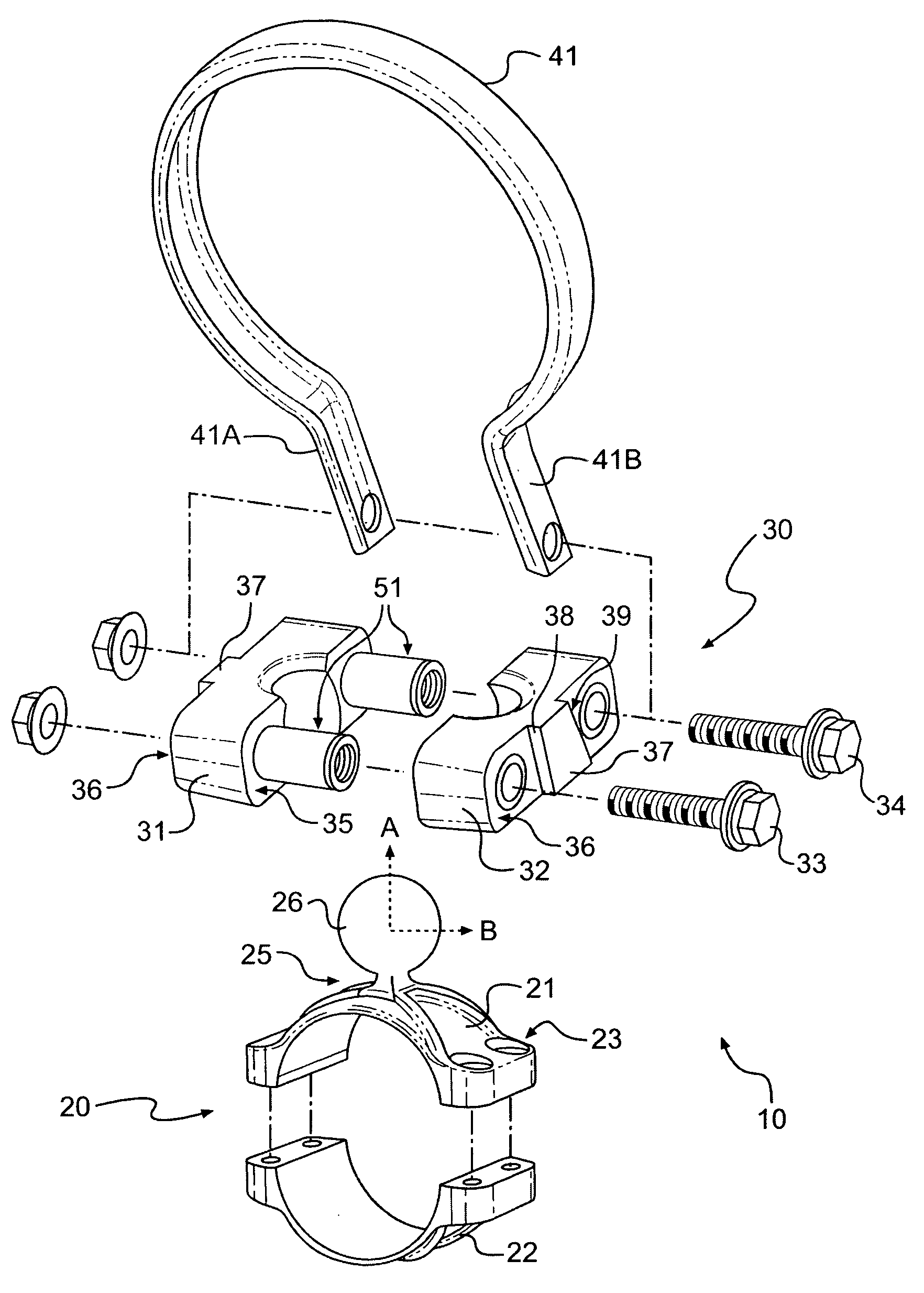
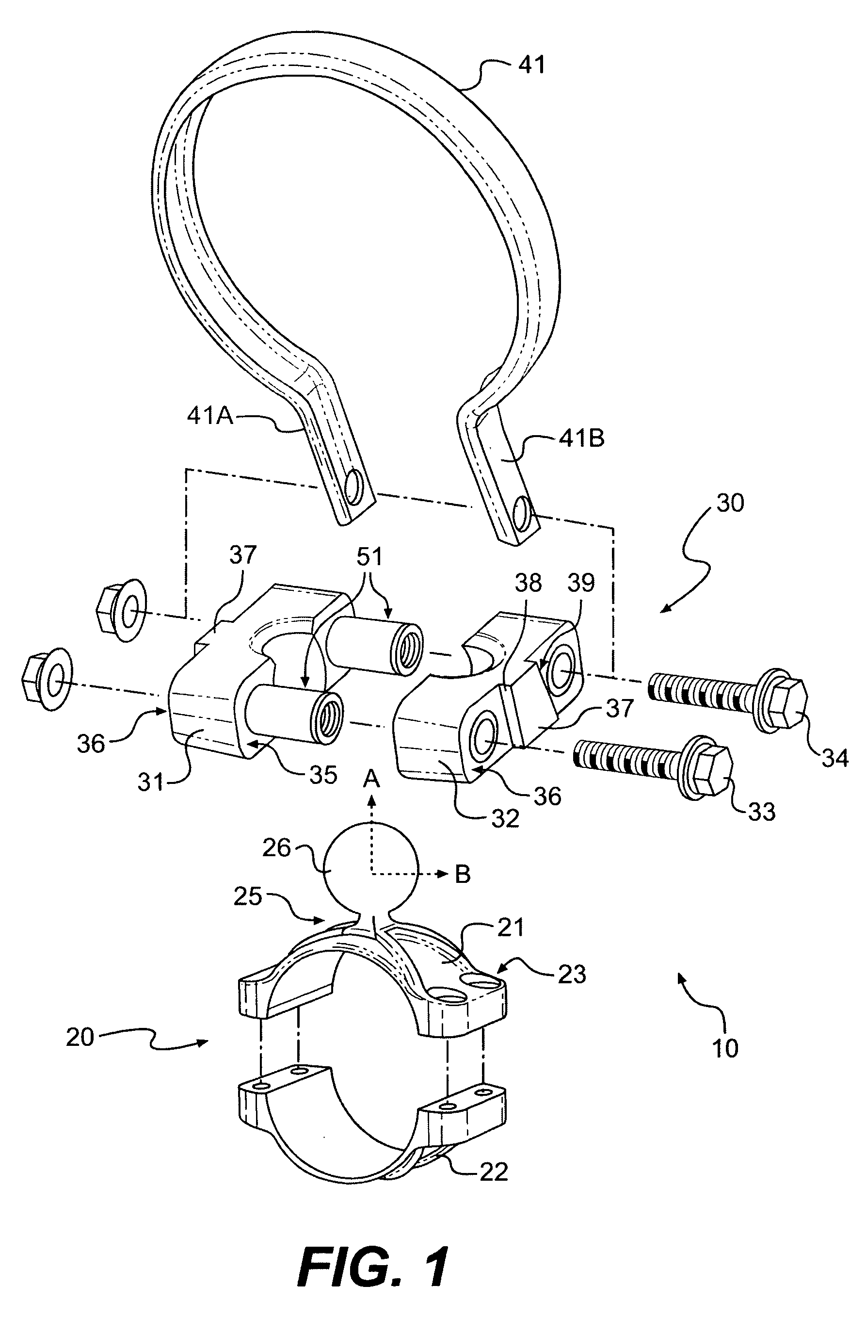
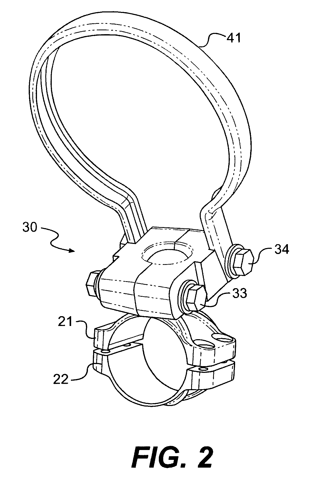
[0035]With reference to the drawings, as shown in FIGS. 1 through 8B, there is provided a gauge mounting assembly 10 having a base member 20, a ball member 26, a ball clamp 30, and a gauge frame member 41. The base member 20 secures the assembly of the present invention to a mounting surface of a vehicle (not shown). Optionally, base member 20 is double split as shown in FIG. 1, and a compression means such as a plurality of fasteners compresses the two portions 21, 22 of the base member 20 uniformly about the mounting surface of the vehicle. The fasteners can extend through openings 23 in the base member 20. A double split clamp is preferred for attaching to tubular portions of a vehicle. Those skilled in the art will recognize that other clamping or mounting arrangements can be employed. For example, as shown in FIGS. 8A and 8B, there is provided a unitary base member 20 for mounting to a flat surface of a vehicle.

[0036]As shown in FIGS. 1, 8A and 8B, a ball member 26 is fixedly s...


PUM


Abstract

An assembly for attaching gauges or other accessories to vehicles provides a base member for securing the assembly to a vehicle surface and a clamp arrangement secured to the base member for superior versatility and customization. The clamp arrangement includes a substantially spherical ball member and a ball clamp, which grips the ball member and allows for the fixed positioning of a gauge frame member to the inner or outer edges of the ball clamp. A tachometer, gauge or other accessory can be secured within the gauge frame member. The ball clamp may be adjusted about the ball member and the gauge frame member can be fixed in different positions to achieve a desired positioning of the gauge. The gauge frame member can be one of a number of designs, including single or double split clamps.

Description

BACKGROUND[0001]1. Field of the Invention[0002]The present invention relates generally to an apparatus for mounting items onto vehicles; more specifically, the invention relates to a rigid and adjustable apparatus for supporting gauges or other items from available areas of vehicles, whether open surfaces or tubular members such as handlebars, roll bars, or A-pillars.[0003]2. Background Information[0004]Some forms of personal transportation lack desired controls, indications, or accessories. Vehicles such as bicycles or snowmobiles offer little space typically considered suitable for instrumentation. Some manufacturers forego such equipment to keep their costs low. These problems provide opportunities for creative after-market solutions. Because of the expense of design and production, after-market manufacturers try to design products applicable to a wide variety of makes or styles of vehicles. Therefore, it is important that after-market solutions be adjustable, capable of suiting ...

Claims


Application Information

Patent Timeline
Patent Type & Authority Patents(United States)
IPC IPC(8): A47B96/00B60R11/00B60R11/02B62JF16B2/06
CPCB60R11/02B62J11/00B60R2011/001B60R2011/0059B60R2011/0071F16B2/065
Inventor DAY, GREGORY E.
Owner GAUGE WORKS
Why Eureka
Try Eureka