Releasable locking mechanisms

a locking mechanism and lock mechanism technology, applied in the direction of screws, traffic signals, roads, etc., can solve the problems of mechanical shock, separation devices are still subject to limitations and disadvantages, and the whole project could be impacted,

Inactive Publication Date: 2005-09-06
NASA
View PDF20 Cites 29 Cited by
  • Summary
  • Abstract
  • Description
  • Claims
  • Application Information

AI Technical Summary

Benefits of technology

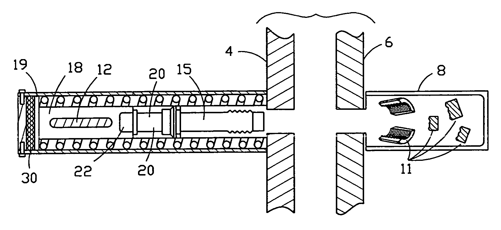
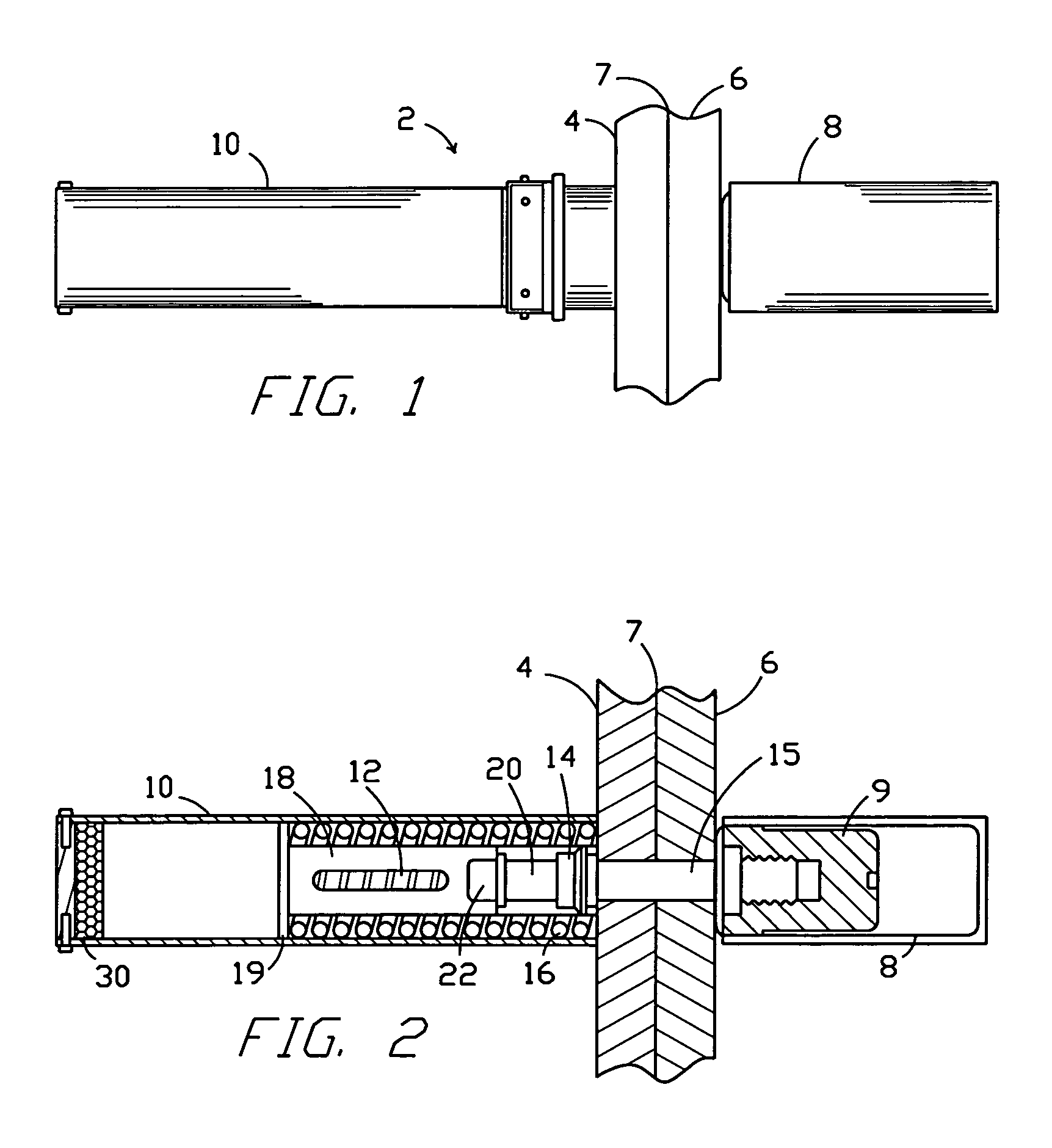
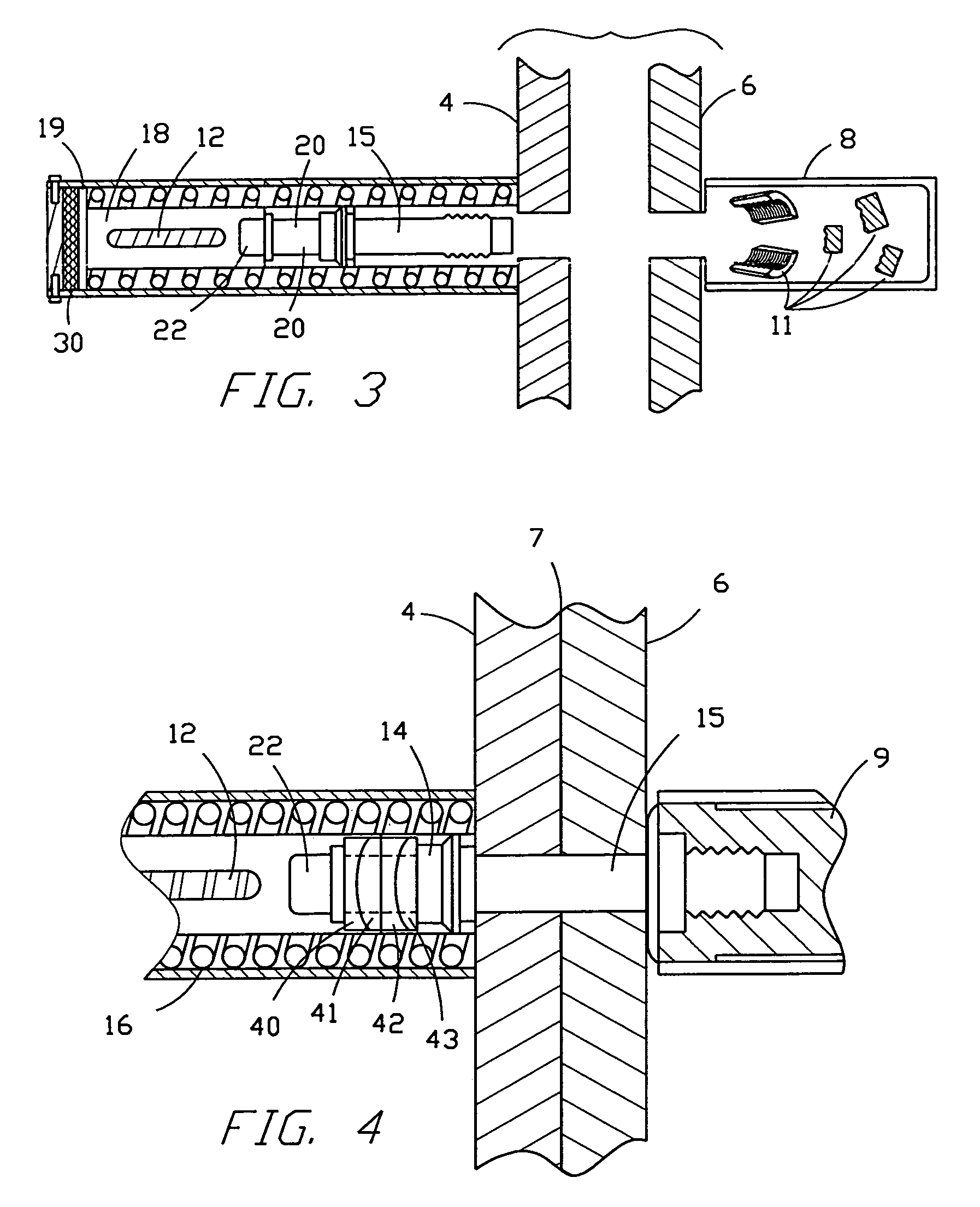
[0009]A releasable locking assembly is the subject of this invention. It is adapted for rapidly separating structures bolted together by a joining bolt and a frangible nut. The locking assembly includes a bolt retractor mechanism adapted to be secured against the structure carrying the head of the joining bolt. The separation nut is attached the bolt end protruding on the other side of the interface plane between the structures. Incorporated in the bolt retractor mechanism are a cylindrical plunger chamber, a coil spring, a plunger, a plunger bolt, and coupling means for attaching the plunger bolt to the joining bolt. The outside surface of the coil spring fits slidably along the inside surface within the cylindrical plunger

Problems solved by technology

If the fastener/separator failed to release on command, an entire project could be imperiled.
The separation devices have been developed in a variety of structures actuated to be separated by pneumatic, hydraulic or pyrotechnic forces generally resulting in mechanical shock.
Despite these improvements separation devices are still subject to certain limitations and disadvantages.
One disadvantage is that pyrotechnic fasteners induce high stresses.
Yet in order to drive pistons, or to fracture nuts or bolts, large shock loads must be produced by the explosive charge.
Even the explosive

Method used


Image

  • Releasable locking mechanisms
  • Releasable locking mechanisms
  • Releasable locking mechanisms

Examples


example 1

Procedure

[0025]A pyrotechnic shock facility was used to perform pyrotechnic tests, shock tests, and pyrotechnic shock tests of both pyrotechnic and nonpyrotechnic systems and components of the invention. The bolt retractor system hardware and test fixtures were bolted to a reaction mass in a test chamber with the forward interference truss and lifting body longeron held in place by test fixtures.

Results

[0026]The test fixtures did not simulate the X-38 vehicle / deorbit propulsion stage separation event, but the functional demonstration showed that the bolt retractor system functioned properly without damaging its components and causing a safety hazard. The demonstration also provided a good estimate of bolt separation timing.

example 2

Procedure

[0027]The X-38 vehicle / deorbit propulsion stage separation event was demonstrated on a Large Mobility Base. It is a large air-bearing simulator which is allowed to float across an epoxy resin floor by three air bearings. It thus acts as an air sled flowing, across the air-bearing floor propelled by air jet thrusters. The function of the large mobility base is to provide a free-floating vehicle and interface for bolt retractor retraction algorithm testing. It is adapted to run either a Windows or Linux operating system. The bolt retractor system of the invention was mounted on the large mobility base. The large mobility base was maneuvered onto a stand and the retractor system bolt was torqued to the required specifications. The nut separation pyrotechnics were fired and the vehicle movement was measured. Two accelerometers and a gyroscope were mounted in the center of mass to sense both the X and Y acceleration compoonents along with yaw rate. Three laser rangefinders were ...

example 3

Procedure

[0029]Proper recording of the precise moment the bolt separation device activated was needed for subsequent data analysis. Since the data acquisition system was on the Large Mobility Base and the pyrotechnic device was stationary, a method was needed for the firing signal to cross the interface without impacting the large mobility base ability to free-float.

Results

[0030]The solution was to use a light emitting diode and phototransistor. The large mobility base mount contained the phototransistor while the light emitting diode was in the base. The light emitting diode was contained in a two-piece mounting bracket created by connecting two base mounts. Alignment pins were used to establish a positive alignment.


PUM


Abstract

In the aerospace field spacecraft components are held together by separation systems until a specific time when they must be separated or deployed. Customarily a threaded joining bolt engages one of the components to be joined, and a threaded nut is placed on that bolt against the other component so they can be drawn together by a releasable locking assembly. The releasable locking assembly herein includes a plunger having one end coupled to one end of a plunger bolt. The other end is flanged to abut and compress a coil spring when the plunger is advanced toward the interface plane between the two components. When the plunger is so advanced toward the interface plane, the end of the plunger bolt can be connected to the joining bolt. Thus during retraction the joining bolt is drawn to one side of the interface plane by the force of the expanding spring.

Description

STATEMENT REGARDING FEDERALLY-SPONSORED RESEARCH OR DEVELOPMENT[0001]The invention described in this patent was made by an employee of the United States Government and may be manufactured and used by or for the Government for governmental purposes without the payment of any royalties.CROSS-REFERENCES TO RELATED APPLICATIONS[0002]There are no applications related to this application.FIELD OF THE INVENTION[0003]Separation systems are widely used in many fields, especially in the aerospace field wherein spacecraft components are held together by a releasable locking assembly until a specific time when they must be separated or deployed. Customarily a headed, threaded bolt engages one of the objects to be joined, and a threaded nut is placed on that bolt against the other object. The nut is threaded into the bolt and tightened. This invention relates generally to such separation systems.BACKGROUND OF THE INVENTION[0004]Separation systems commonly used in aerospace engineering and in oth...

Claims


Application Information

Patent Timeline
IPC IPC(8): F16D1/00F16B1/00F16B31/00
CPCF16B31/00Y10T403/1683Y10T403/18Y10T403/11F16B2200/63
Inventor AHMED, RAFIQWINGATE, ROBERT J.
Owner NASA
Why Eureka
Try Eureka