Assembly of a drive shaft with the cutting head hub of a submersible granulator

Inactive Publication Date: 2005-09-06
BKG BRUCKMANN & KREYENBORG GRANULIERTECHNIK GMBH
View PDF12 Cites 4 Cited by
  • Summary
  • Abstract
  • Description
  • Claims
  • Application Information

AI Technical Summary

Benefits of technology

[0013]The invention is based on the task of creating a self-aligning connection between drive shaft and cutting head disc that is capable of transmitting large forces without difficulty, these for

Problems solved by technology

Thus, compared to this prior art, a co

Method used


Image

  • Assembly of a drive shaft with the cutting head hub of a submersible granulator
  • Assembly of a drive shaft with the cutting head hub of a submersible granulator
  • Assembly of a drive shaft with the cutting head hub of a submersible granulator

Examples


Embodiment Construction

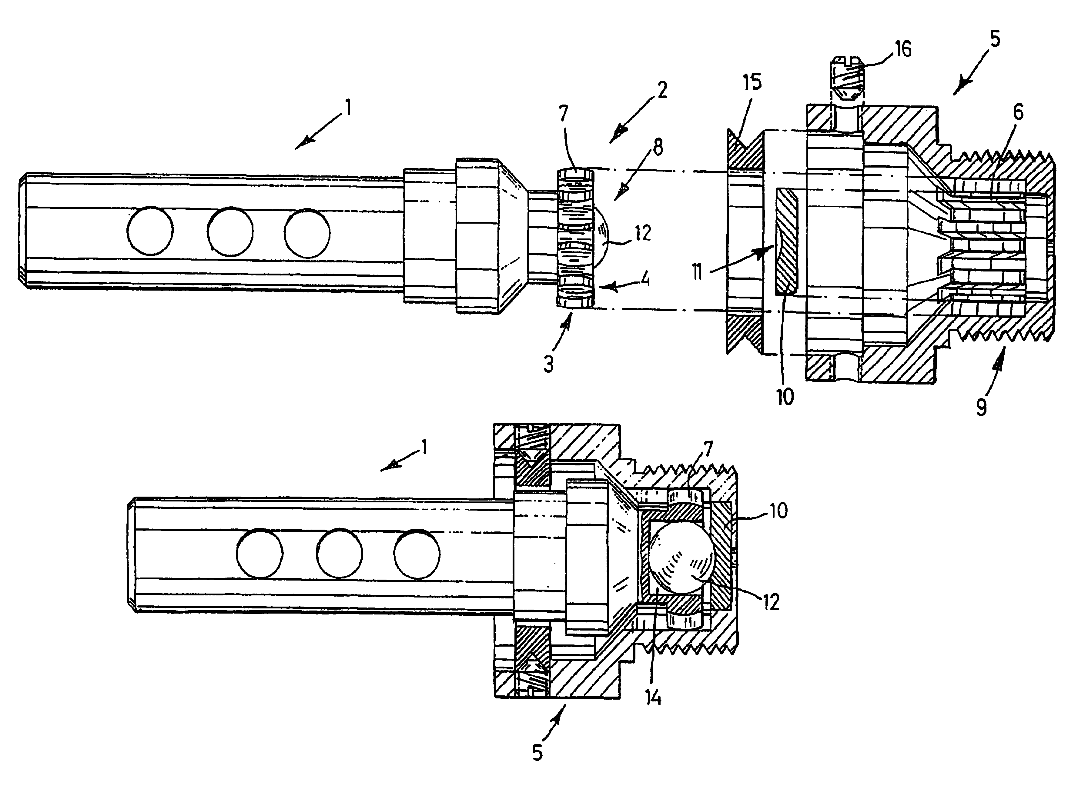
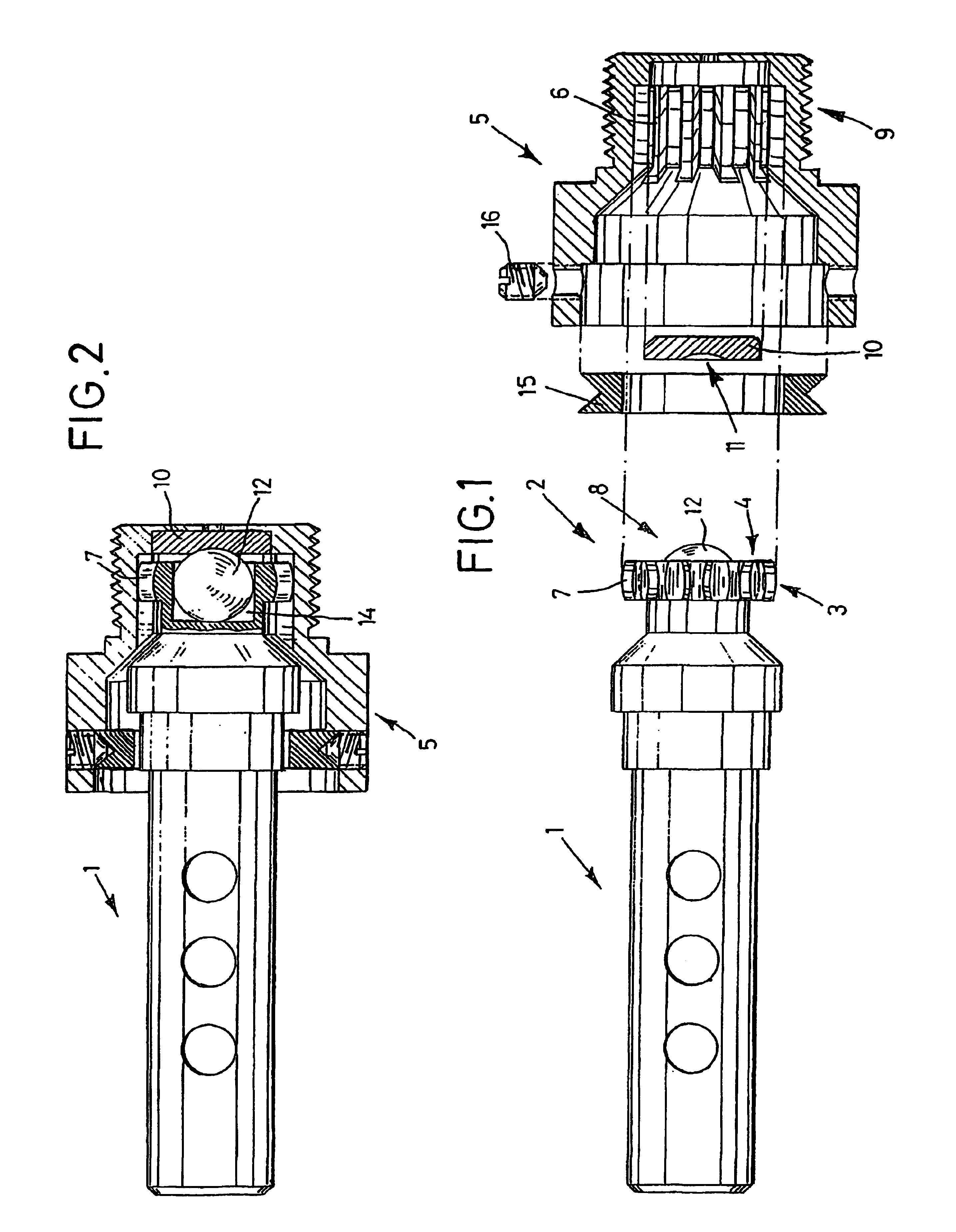
[0026]In the drawings, 1 indicates a drive shaft, which at its end 2 pointing toward the cutting edge head to be attached (not shown in the drawing) displays outer cogs 3 that are formed by a cogged crown 4, which displays individual cogs 7. The outer cog surface of each cog 7 is here designed in a convexly-curved manner, as can readily be seen from the drawing, and in the represented embodiment example the cog flanks of the cogs 7 are also convexly curved around an axis running parallel to the longitudinal axis of the drive shaft; in other words, each cog 7 is in itself broader at its center than at the ends. The convex curving of the outer cog surfaces is essential, while the convex curving of the cog flank surfaces is not of such great significance and can be dispensed with, for example for reasons relating to finishing technology.

[0027]The drive shaft 1 displays, at the end 2 pointed toward the cutting head disc, a ball end 8; this ball end 8, as FIG. 2 clearly shows, is formed ...


PUM

PropertyMeasurementUnit
Pressureaaaaaaaaaa

Abstract

The invention relates to the assembly of a drive shaft with the cutting head hub of a submersible granulator. Said assembly comprises a connector hood which can be fixed to the drive shaft in such a way that it remains free to move. The connector hood is provided with threading for screwing the cutting head hub onto the drive shaft, said drive shaft being supported on a spherical extremity situated on the inside of the connector hood, and a cogged crown with inner-sided cogs is placed on the cutting head side of the drive shaft. The connector hood has inner-sided cogs which interlace with the cogs on the outer side of the cogged crown. The outer surface of each cog on the cogged crown is convex.

Description

CROSS-REFERENCE TO RELATED APPLICATIONS[0001]Not ApplicableSTATEMENT REGARDING FEDERALLY SPONSORED RESEARCH OR DEVELOPMENT[0002]Not ApplicableINCORPORATION-BY-REFERENCE OF MATERIAL SUBMITTED ON A COMPACT DISC[0003]Not ApplicableBACKGROUND OF THE INVENTION[0004]1. Field of the Invention[0005]The invention relates to an assembly of a drive shaft with the cutting head hub of a submersible granulator according to the preamble of the main claim.[0006]2. Description of Related Art[0007]Self-aligning cutting head hubs for the assembly of the cutting head hub with a drive shaft are known, whereby the self-aligning hub enables the knife blades of the cutting head disc to assume an optimal parallel arrangement with respect to the counteredges or to the extrusion-nozzle plates.[0008]In the arrangement according to DE 196 42 389 A1, inserted into the cutting head disc is a hub that can adjust itself with respect to the plane of the cutting head disc, so that the possibility thereby exists of th...

Claims


Application Information

Patent Timeline
IPC IPC(8): B29B9/06B29B9/02F16D3/16F16D3/18B01J2/20B26D7/26
CPCB29B9/065F16D3/185
Inventor BRUCKMANN, THEODOR
Owner BKG BRUCKMANN & KREYENBORG GRANULIERTECHNIK GMBH
Why Eureka
Try Eureka